
Turning Away From (Some) Tooling Conventions - cnc machine insert name
With both GC4425 and GC4415, the insert’s substrate and coating have been developed to better withstand high temperatures. Both contain a second-generation Inveio® layer, a textured chemical vapour deposition (CVD) alumina (Al2O3) coating developed for machining. Inveio creates a strong barrier towards the cutting zone and extends the life and wear resistance of tools.
Sandvik Coromant, part of the Sandvik group headquartered in Sandviken, Sweden, has announced that it is adding two new steel-turning carbide grades – GC4415 and GC4425 – to its range in an effort to improve cutting speeds and reduce energy consumption. Sandvik Coromant has reported that an average tool life increase of 25%, in combination with reliable and predictable performance can minimise materialise waste.
The C-type insert, on the other hand, has a much better positioning from this point of view, since two of its sides are all positioned in the insert slot. This aspect becomes important when we have to start using the inserts in roughing operations when depth of cut and feed rates are high. The fact of having better stability in the case of the C insert is a fundamental advantage for cutting edge life and machining success.
Join thousands of other PM professionals and get the latest industry news, deep dive articles and more, to your inbox.
Because of its versatility and not only because of the number of operations it can perform but also because of the number of possible applications, from roughing to finishing, the C-type insert is undoubtedly the most widely sold and used insert in machine shops all over the world. It could be said that the C shape combined with its 95° lead angle has made the fortune not only of the insert manufacturers but also of us operators and workshop technicians, who have solved many problems with the use of this tool. In addition, the C shape placed on a different tool with a different lead angle would have a way of working with the so-called 100° recovery angle. In this way, the C-type insert would have 4 cutting edges instead of 2, making it one of the most affordable inserts.
Used with recovery angles, it would certainly not be able to perform countless movements on the workpiece or remove large amounts of material. But within its field of application it would remain useful, also because the recovery angle assumes that the insert works at an angle between the cutting edges of 100°, so it is also very strong. This solution is successfully used in various sectors, for example when machining the surfaces of forged parts, roughing eccentric components where the interrupted cut affects the life of the insert. The first cut is often made in this way in order to improve and optimise production costs.
Let’s take a closer look at some practical aspects of the C and W shape inserts. Let’s compare them on the assumption that they have the same nose radius, the same solid carbide grade and identical chipbreaker geometry.
Reach a truly international audience that includes component manufacturers, end-users, industry suppliers, analysts, researchers and more.
First of all, let’s start by counting the number of cutting edges useful for our machining; the trigonal insert with its 6 cutting edges would be the master. The more cutting edges, the more pieces produced. Moreover, since the purchase cost of both inserts would be the same, the cost per cutting edge would be considerably in favour of the W-type insert; therefore, it will be cheaper per cutting edge. The W-type insert would definitely be the winner so far.

GC4425 is said to deliver improved wear resistance, heat resistance and toughness, while grade GC4415 is designed to complement GC4425 when enhanced performance and more heat resistance is needed. Both grades are suitable for use with tough materials like Inconel and unalloyed stainless steel ISO-P grades that are complex and difficult to machine.
First of all, I would like to remind you that you can download the scheme of the ISO insert nomenclature. Keep it handy during today’s lesson and the next one, by clicking on the icon at the bottom right of the video. It will also come in handy on the machine. ISO insert nomenclature In today’s lesson we looked at the first part of the ISO insert nomenclature for mechanically fixed inserts. To be precise we looked at the first 4 letters. The first letter of the code is perhaps the most important one, that is the one that every turner must surely know because it defines the shape of the insert. In this lesson we have seen them all, although as we have said, in reality the most common shapes are as follows: As we said in the lesson, the choice of shape influences the strength of the insert and its versatility in making profiles. Among the various shapes, we find exactly in the centre the C and W shapes. Both have an angle between the cutting edges of 80° and both, for one reason or another, are among the most popular. C and W in comparison Let’s take a closer look at some practical aspects of the C and W shape inserts. Let’s compare them on the assumption that they have the same nose radius, the same solid carbide grade and identical chipbreaker geometry. C and W have different shapes – the first trigonal and the second rhomboidal – but both, once placed on the respective tool, tackle the machining with the same 95° tool cutting edge angle and therefore with a 5° lead angle. From the point of view of versatility, so the number of possible operations, both tools would be similar. Therefore they would be able to carry out the exact same machining operations for us operators: turning of various types, shouldering, chamfers and radius. So which one are we going to use? First of all, let’s start by counting the number of cutting edges useful for our machining; the trigonal insert with its 6 cutting edges would be the master. The more cutting edges, the more pieces produced. Moreover, since the purchase cost of both inserts would be the same, the cost per cutting edge would be considerably in favour of the W-type insert; therefore, it will be cheaper per cutting edge. The W-type insert would definitely be the winner so far. But does this way of thinking fit well with our chip volume and productivity? Is this really the most economical way? Of course, we would say yes if we stopped at this level. But we like to go into each topic in depth, so let’s think about it. Look at how the inserts are mounted on their respective tools; we should notice that the W-shaped insert would offer a slot with a more open contact angle due to its shape. The C-type insert, on the other hand, has a much better positioning from this point of view, since two of its sides are all positioned in the insert slot. This aspect becomes important when we have to start using the inserts in roughing operations when depth of cut and feed rates are high. The fact of having better stability in the case of the C insert is a fundamental advantage for cutting edge life and machining success. It is probable that the W-type insert will fail when heavily loaded due to the micro-vibrations created by the precarious fixing. Consequently, it is no longer so certain that we can use all 3 of its cutting edges, contrary to what happens with the C-shaped insert where we can certainly use both cutting edges. In our opinion, it should be used, for example, on machines where the working data are not so demanding. Its operations could be finishing and semi-finishing on materials that are not particularly difficult to machine. Because of its versatility and not only because of the number of operations it can perform but also because of the number of possible applications, from roughing to finishing, the C-type insert is undoubtedly the most widely sold and used insert in machine shops all over the world. It could be said that the C shape combined with its 95° lead angle has made the fortune not only of the insert manufacturers but also of us operators and workshop technicians, who have solved many problems with the use of this tool. In addition, the C shape placed on a different tool with a different lead angle would have a way of working with the so-called 100° recovery angle. In this way, the C-type insert would have 4 cutting edges instead of 2, making it one of the most affordable inserts. Used with recovery angles, it would certainly not be able to perform countless movements on the workpiece or remove large amounts of material. But within its field of application it would remain useful, also because the recovery angle assumes that the insert works at an angle between the cutting edges of 100°, so it is also very strong. This solution is successfully used in various sectors, for example when machining the surfaces of forged parts, roughing eccentric components where the interrupted cut affects the life of the insert. The first cut is often made in this way in order to improve and optimise production costs.
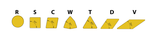
The first letter of the code is perhaps the most important one, that is the one that every turner must surely know because it defines the shape of the insert. In this lesson we have seen them all, although as we have said, in reality the most common shapes are as follows:
As we said in the lesson, the choice of shape influences the strength of the insert and its versatility in making profiles.
C and W have different shapes – the first trigonal and the second rhomboidal – but both, once placed on the respective tool, tackle the machining with the same 95° tool cutting edge angle and therefore with a 5° lead angle. From the point of view of versatility, so the number of possible operations, both tools would be similar. Therefore they would be able to carry out the exact same machining operations for us operators: turning of various types, shouldering, chamfers and radius.
Don't miss any new issue of PM Review, and get the latest industry news. Sign up to our weekly newsletter.
The GC4425 grade was subjected by Sandvik Coromant’s customers to pre-market tests. Among these was a general engineering company that applied both a competitor’s insert and the GC4425 insert, in the manufacture of pressure rollers. An ISO-P grade was subjected to continual external axial machining and semi-finishing at a cutting speed (vc) of 200 m/min, feed rate of 0.4 mm/rev (fn) and depth (ap) of 4 mm.
Look at how the inserts are mounted on their respective tools; we should notice that the W-shaped insert would offer a slot with a more open contact angle due to its shape.
The company has stated that this illustrates the gains that can be achieved if the right machining elements are brought together. To help with process monitoring itself, Sandvik Coromant has also developed CoroPlus® Process Control software that can monitor machining in real-time and act according to programmed protocols if specific issues occur — for example, by stopping the machine or replacing a worn cutting tool.
Among the various shapes, we find exactly in the centre the C and W shapes. Both have an angle between the cutting edges of 80° and both, for one reason or another, are among the most popular.
Manufacturers typically measure tool life by the number of workpieces machined. While competitor’s grade machined a reported twelve pieces before wearing out due to plastic deformation, Sandvik Coromant’s insert produced eighteen pieces and, in doing so, worked 50% longer with stable and predictable wear.
First of all, I would like to remind you that you can download the scheme of the ISO insert nomenclature. Keep it handy during today’s lesson and the next one, by clicking on the icon at the bottom right of the video. It will also come in handy on the machine.
In today’s lesson we looked at the first part of the ISO insert nomenclature for mechanically fixed inserts. To be precise we looked at the first 4 letters.
Extensive Powder Metallurgy industry news coverage, and the following exclusive deep-dive articles and reports:
In our opinion, it should be used, for example, on machines where the working data are not so demanding. Its operations could be finishing and semi-finishing on materials that are not particularly difficult to machine.
But does this way of thinking fit well with our chip volume and productivity? Is this really the most economical way? Of course, we would say yes if we stopped at this level. But we like to go into each topic in depth, so let’s think about it.
The GC4425 grade reputedly provides extremely high process security through its ability to retain an intact edge line. Because the insert can deliver more pieces per edge, fewer carbides are consumed to machine the same number of components; consistence and predictability also help to minimise material waste.
It is probable that the W-type insert will fail when heavily loaded due to the micro-vibrations created by the precarious fixing. Consequently, it is no longer so certain that we can use all 3 of its cutting edges, contrary to what happens with the C-shaped insert where we can certainly use both cutting edges.
The free-to-access PM Review magazine archive offers unparalleled insight into the world of Powder Metallurgy from a commercial and technological perspective through:
Discover suppliers of these and more in our advertisers’ index and buyer’s guide, available in the back of PM Review magazine.


 18581906093