
ANSI and ISO Insert Designations - turning insert description
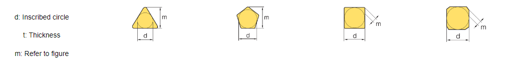
For insert shapes such as round, square, triangle & trigon, this would then indicate the diameter of the inscribed circle (IC).
Features: 1. High durability,precision,wear resistance,toughness and combination abilities. 2. Good surface roughness of finish, high quality are satisfactory
Each member brings with them their own experience and know-how to add to our growing pool of technical knowledge. That’s why our services are known for being the best in the business!
Tolerance dimensions are indicated by a letter ranging from A - U. Dimension A relates to the inscribed circle (IC), dimension B relates to the insert height (for pentagon, triangle, and trigon shapes – for other polygons, the dimension B relates to the distance that is measured along the bisector of the corner angle) and dimension T relates to the thickness of the insert.
All turning inserts have a unique ISO code that contains various letters and numbers – believe it or not, these actually mean something! From just looking at the ISO code you can figure out the insert’s shape, relief angle, tolerance, cross-section type, cutting-edge length, thickness, radius, and chip breaker!
GER100-D Indexable Tungsten Carbide Grooving Inserts Cnc Grooving Tool Cutters Carbide threading inserts: Carbide threading inserts are the most common material type, as they allow for higher cutting speeds than tool steel and can retain a sharper cutting edge. Available as external or internal threading inserts, they usually fit into a right-hand toolholder that is specifically designed to accept inserts. Features: 1. High durability,precision,wear resistance,toughness and combination abilities. 2. Good surface roughness of finish, high quality are satisfactory Advantage: 1. Recommending more suitable processing parameters. 2. OEM and ODM applicable. 3. Suggsting more suitable model to replace any other brands. 4. Offering together with tool holder model dimensions holder W B r A L T d GER050-A GEL050-A 0.5 1.2 0.05 6.69 6.5 2.58 3.5 SIGER/L***A GER080-A GEL080-A 0.8 1.2 0.05 GER100-A GEL100-A 1.0 1.5 0.05 GER120-A GEL120-A 1.2 1.5 0.05 GER150-A GEL 150-A 1.5 1.5 0.1 GER180-A GEL 180-A 1.8 1.5 0.1 GER200-A GEL 200-A 2.0 1.5 0.1 GER080-B GEL 080-B 0.8 1.8 0.05 8.46 8.2 3.18 2.7 SIGER/L***B GER100-B GEL 100-B 1.0 2.2 0.05 GER120-B GEL 120-B 1.2 2.2 0.05 GER150-B GEL 150-B 1.5 2.2 0.1 GER180-B GEL 180-B 1.8 2.2 0.1 GER200-B GEL 200-B 2.0 2.2 0.1 GER250-B GEL 250-B 2.5 2.2 0.1 GER280-B GEL 280-B 2.8 2.2 0.2 GER300-B GEL 300-B 3.0 2.2 0.2 GER100-C GEL 100-C 1.0 2.5 0.05 5.8 11.4 8 4.05 2.8 SIGER/L***C GER120-C GEL 120-C 1.2 2.5 0.05 GER140-C GEL 140-C 1.4 2.5 0.1 GER150-C GEL 150-C 1.5 2.5 0.1 GER180-C GEL 180-C 1.8 2.2 0.1 GER200-C GEL 200-C 2.0 2.2 0.1 GER250-C GEL 250-C 2.5 2.2 0.2 GER300-C GEL 300-C 3.0 2.2 0.2 GER350-C GEL 350-C 3.5 2.2 0.2 GER100-D GEL 100-D 1.0 2.5 0.05 6.8 16.4 4 5.05 3.4 SIGER/L***D GER120-D GEL 120-D 1.2 2.5 0.05 GER150-D GEL 150-D 1.5 3.0 0.1 GER200-D GEL 200-D 2.0 3.6 0.1 GER250-D GEL 250-D 2.5 3.6 0.2 GER300-D GEL 300-D 3.0 4.5 0.2 GER350-D GEL 350-D 3.5 4.5 0.2 GER400-D GEL 400-D 4.0 4.5 0.2 GER150-E GEL 150-E 1.5 3.0 0.1 9.54 21.6 6 5.55 4.4 SIGER/L***E GER200-E GEL 200-E 2.0 3.8 0.1 GER250-E GEL 250-E 2.5 4.5 0.2 GER300-E GEL 300-E 3.0 4.5 0.2 GER350-E GEL 350-E 3.5 5.5 0.2 GER400-E GEL 400-E 4.0 5.5 0.2 GER450-E GEL 450-E 4.5 6.5 0.2 GER500-E GEL 500-E 5.0 6.5 0.2 model dimensions holder W B r A L T d GER100-050AR GEL150-050AR 1.0 1.5 0.5 6.69 6.5 2.58 2.5 SIGER/L*A GER150-075AR GEL150-075AR 1.8 1.5 0.75 GER200-100AR GEL200-100AR 2.0 1.5 1.0 GER100-050BR GEL100-050BR 1.0 2.2 0.5 8.46 8.2 3.18 2.7 SIGER/L*B GER150-075BR GEL150-075BR 1.5 2.2 0.75 GER200-100BR GEL 200-100BR 2.0 2.2 1.0 GER300-150BR GEL300-150BR 3.0 2.2 1.5 GER100-050CR GEL100-050CR 1.0 2.5 0.5 5.8 11.48 4.05 2.8 SIGER/L*C GER150-075CR GEL150-075CR 1.5 2.5 0.75 GER200-100CR GEL200-100CR 2.0 2.5 1.0 GER300-150CR GEL300-150CR 3.0 2.5 1.5 GER200-100DR GEL200-100DR 2.0 3.2 1.0 6.8 16.44 5.05 3.4 SIGER/L*D GER300-150DR GEL300-150DR 3.0 4.5 1.5 GER400-200DR GEL400-200DR 4.0 4.5 2.0 GER300-150ER GEL300-150ER 3.0 5.5 1.5 9.54 21.66 5.55 4.4 SIGER/L*E GER400-200ER GEL400-200ER 4.0 6.5 2.0 GER500-225ER GEL200-225ER 5.0 6.5 2.25 model dia. dimensions W B r A L T d GER100DM06-D Dï¼6 1.0 2.5 0.1 6.8 16.44 5.05 3.4 GER150DM10-D Dï¼10 1.5 2.8 0.2 GER200DM10-D Dï¼10 2.0 3.5 0.2 GER250DM15-D Dï¼15 2.5 4.5 0.2 GER300DM15-D Dï¼15 3.0 4.5 0.2 GER400DM15-D Dï¼15 4.0 4.5 0.2 GER-D Circlip grooving holder model insert h/b L screw ætrox SEGEL1212D GER**-D 12 100 M3*10 T10 SEGEL1616D 16 125 SEGEL2020D 20 125 SEGEL2525D 25 150 FAQ: Q: Why customers choose us? A: Competitive price,high quality,fast delivery,patiently pre-sales consultation and perfect after-sales service. And we are manufactures ,have our own factory ,we can Guarantee our quality. Q: What's the MOQ? A: Usually MOQ is one box,10 pcs/box, some special is 5 pcs/box or 2 pcs/box. Q: How long is your delivery time? A: Generally 3-7 work days if the quantity 1-500 pcs,more than 500 pcs,need to negotiate. Q: How does your factory to control quality? A: Quality is priority. we will do 100% quality inspection before shipment. Q: What is payment method? A: Normally T/T, Western union,Pay pal ,Credit card. Q: Do you accept trial order? A: Yes,u can order with small amount to test.
In this blog, we will discuss how to identify all these key dimensions, so you will never need to check for part numbers again.
The nose radius of an insert can affect the performance. A larger nose radius can result in the use of higher feed rates, and larger depths of cut, and they can handle more pressure, making them much better for heavier metal removal. Whereas a turning insert with a smaller nose radius can only take smaller depths of cut, they also have weaker cutting edges, and they can only handle a small amount of vibration but are much better for finishing as they are sharper and have less surface contact.
It plays a crucial role in chip formation, tool life, cutting forces, and surface finish. Understanding the influence of the relief angle and selecting the appropriate one can greatly enhance machining performance, productivity, and the quality of the finished product.
The cross-section highlights the differences in the design of the insert, such as the fixing holes, countersinks, and special features. This dictates what clamping method would be used to fix the insert on to the tool holder.
Some of the below chipbreakers are available on both negative and positive inserts but the min-max depths of cut may vary.
It is a 2-digit number that generally indicates the width or length, however this is only applicable to insert shapes with no IC (inscribed circle), such as rectangular and parallelograms.
The relief angle for a milling insert is of paramount importance in achieving efficient and successful machining operations.
The thickness of a turning insert is measured from the bottom of the insert to the top of the cutting edge. This will be shown as a 2-digit number except where the insert features a T and then a single digit number eg T3. This is due to the fact that there are more than one increment within each mm. eg 03 is 3.18mm whereas T3 is thickest at 3.97mm.
Choosing the right insert shape for your turning tool is essential. The shape of the insert can affect the vibration during operation, the ability to turn complex contours, the strength of the insert and its ability to take bigger and heavier cuts.
The chip breaker is represented as 2 letters in the ISO code. The chip breaker affects the cutting resistance, if the cutting resistance is low, it can avoid chipping and fracturing of the cutting edges. Reduced cutting resistance can also decrease the tool load and heat built up. The chip breaker also determines the depth of cut the insert can take, if you are not applying the correct depth of cut then you won’t be activating the chip breaker, this can cause the swarf to build up and become stringy, some people refer to this as a bird’s nest.


 18581906093