
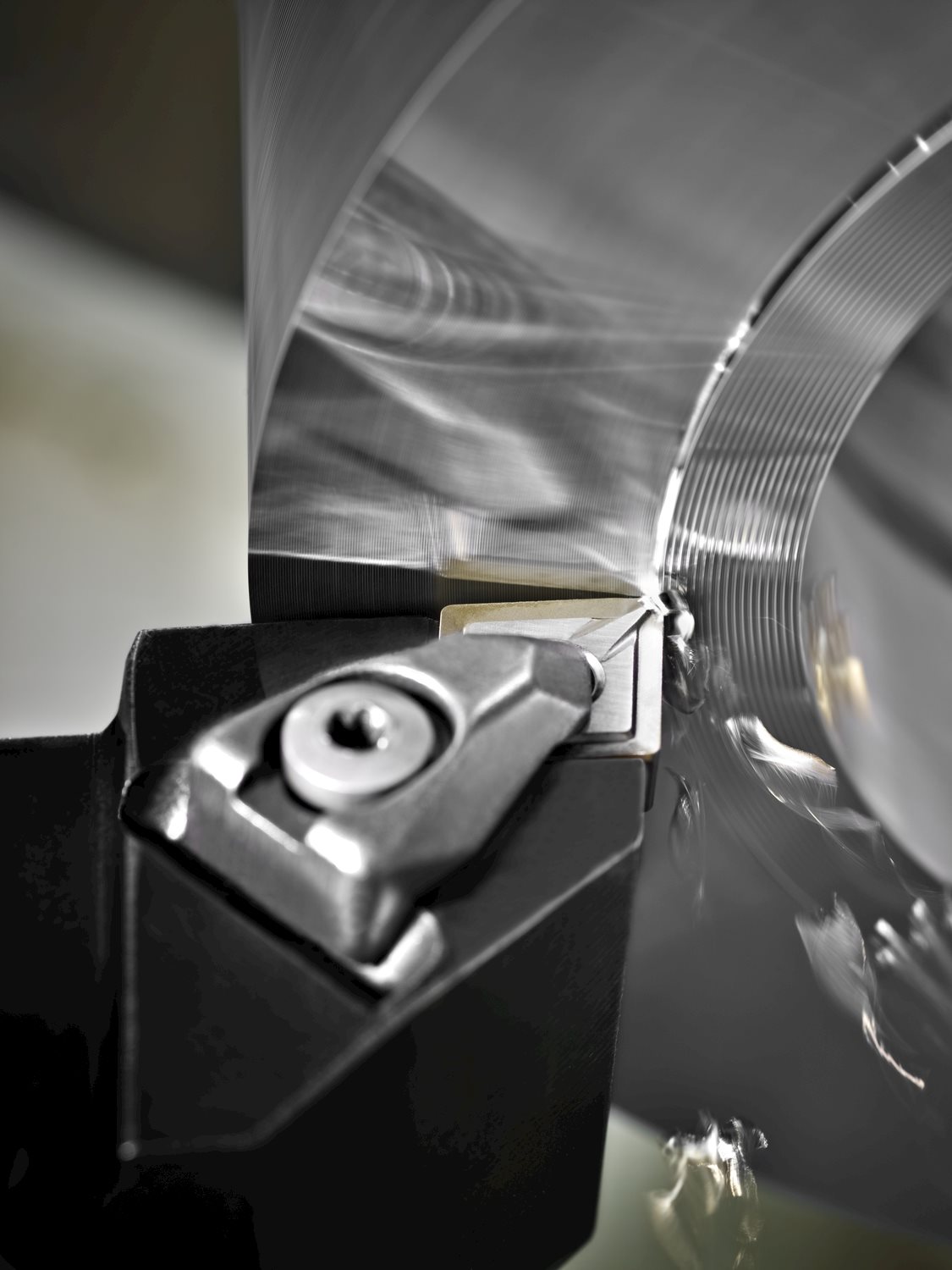
Diamond turning - diamond turning insert
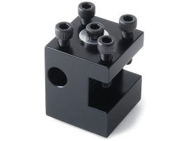
The problem is when the clamp is tightened, the inside corner makes contact with the step next to the holder insert pocket. This prevents the clamp from making full contact with the clamping notch in the top of the insert. We used to buy these clamps, but they are no longer available, so we started making them in-house. We initially designed them with symmetrical angle cuts on each side of the clamp nose, but they should not be the same. We have since changed the inside angle.
CAUTION: Chips coming off the carbide inserts can be very HOT! Use extreme caution. Carbide inserts can also shatter. For these reasons, proper protective eyewear and clothing are especially important when using these tools.
The ME and MD geometries can be an optimization of the M geometry, depending on the identified wear pattern or machining behavior.
A bridge geometry between E and M, ME provides the lighter cutting action and chip formation of an M geometry with less risk of edge chipping and breakage than with an E geometry. It is used more as an optimization of the M geometry than the E geometry because of its macro-geometry design. In comparison to the M geometry, ME has a higher rake angle and a smaller or more positive protection chamfer. This design is ideal for reducing cutting forces, chip thicknesses and built-up edges on low- to medium-alloyed steels, softer stainless steels and superalloy materials.
In addition to grade, the insert geometry has a tremendous impact on the machining process and the way the grade behaves and wears. A hard grade combined with a geometry that is too sharp can easily chip and fracture when performing extreme interrupted cuts or inclusions.
Only about a dozen defective clamps were shipped. Contact us immediately if you received one of these clamps. We will replace any clamps, free of charge, that are found to be defective.
In addition to grade, the insert geometry has a tremendous impact on the machining process and the way the grade behaves and wears. A hard grade combined with a geometry that is too sharp can easily chip and fracture when performing extreme interrupted cuts or inclusions.Conversely, extreme thermal and abrasive conditions will adversely impact tool life on an insert with a tough grade and heavily protected geometry. Optimizing your tool life and application is always a balance between insert grade and geometry.The Seco geometry naming convention provides guidance as to how geometry affects the insert’s cutting action. M = Medium (e.g. XOMX120408TR-M12 MP2501)M indicates “medium” geometries. They are often an excellent first choice and used in many applications due to their versatility when it comes to material, cutting and wear behavior. Mid-level vibrations, heterogenous workpiece conditions as inclusions or raw skin, medium to higher tensile stress materials as well as moderate feed rates can be machined with this geometry type. M geometries are a strong go-to choice for the core materials of steels, cast iron and stainless steels.The ME and MD geometries can be an optimization of the M geometry, depending on the identified wear pattern or machining behavior.ME geometry: to reduce cutting forces or built-up edgesMD geometry: to reduce edge chipping or breakageFor more information about ME and MD geometries, see below. ME = Medium – Easy (e.g. XOMX120408TR-ME08 T350M)A bridge geometry between E and M, ME provides the lighter cutting action and chip formation of an M geometry with less risk of edge chipping and breakage than with an E geometry. It is used more as an optimization of the M geometry than the E geometry because of its macro-geometry design. In comparison to the M geometry, ME has a higher rake angle and a smaller or more positive protection chamfer. This design is ideal for reducing cutting forces, chip thicknesses and built-up edges on low- to medium-alloyed steels, softer stainless steels and superalloy materials. MD = Medium – Difficult (e.g. XOMX120408TR-MD13 MP1501)To reduce edge chipping or breakage under the higher mechanical loads of high tensile stress materials, high feed rates under stable cutting conditions or cutting edge chipping due to vibrations or inclusions, the MD geometry uses a more negative protected cutting edge than M geometry but provides lighter cutting in comparison to a D geometry. MD geometry is typically used for tough or high-performance cast iron roughing applications, medium to higher alloyed steels and hardened steels. E = Easy (e.g. XOEX120408FR-E06 H15)E stands for “easy” cutting and is perfect for low-strength materials such as non-ferrous metals or low-alloyed steels and stainless steels. The geometry is sharp without any protection chamfer and has a high rake angle to reduce cutting forces and plastic deformation during chip formation. This geometry is suitable for all metals that deform easily and tend to cause built-up edges. Typically, uncoated or PVD-coated grades are offered in this combination to keep the sharp characteristic of this geometry, since thicker CVD coatings are too brittle and too thick to stick to these sharp cutting edges. D = Difficult (e.g. XOMX120408TR-D14 MK1500)The D geometry provides the highest edge protection with low rake angles for a strong cutting wedge angle. Applications in hard steels, high tensile stress steels or materials with extremely hard inclusions such as cast iron require stable cutting edges that withstand high dynamic mechanical loads without easily breaking. D geometry is also suitable when facing extreme vibrations that cannot be reduced or avoided by changing the cutting parameters to a more suitable working range. D geometry can generate high cutting forces and temperatures and may need to be optimized to M or MD geometries for lighter cutting and reduced vibrations in particular applications.
To get up and going right now, if you have a bench grinder or file, grind the backside of the clamp (circled in blue in the picture) until the tip of the clamp clears the step (shown by the red arrow). Then the clamp will lock the insert in place as it should.
M indicates “medium” geometries. They are often an excellent first choice and used in many applications due to their versatility when it comes to material, cutting and wear behavior. Mid-level vibrations, heterogenous workpiece conditions as inclusions or raw skin, medium to higher tensile stress materials as well as moderate feed rates can be machined with this geometry type. M geometries are a strong go-to choice for the core materials of steels, cast iron and stainless steels.
The D geometry provides the highest edge protection with low rake angles for a strong cutting wedge angle. Applications in hard steels, high tensile stress steels or materials with extremely hard inclusions such as cast iron require stable cutting edges that withstand high dynamic mechanical loads without easily breaking. D geometry is also suitable when facing extreme vibrations that cannot be reduced or avoided by changing the cutting parameters to a more suitable working range. D geometry can generate high cutting forces and temperatures and may need to be optimized to M or MD geometries for lighter cutting and reduced vibrations in particular applications.
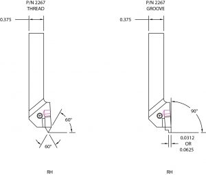
Sherline now manufactures its own inserted tip threading and grooving holder. Because of the multiple uses and the cost of the inserts, the holder is sold separately with no inserts included. You choose which inserts you need and order them separately. A special clamp, 6-32 hold-down screw, and 7/64″ hex key are included with the holder.
It has come to our attention that there may be issues with some of our Threading/Grooving Carbide Insert Tool Holders (P/N 2267) not securely clamping the cutting inserts.
E stands for “easy” cutting and is perfect for low-strength materials such as non-ferrous metals or low-alloyed steels and stainless steels. The geometry is sharp without any protection chamfer and has a high rake angle to reduce cutting forces and plastic deformation during chip formation. This geometry is suitable for all metals that deform easily and tend to cause built-up edges. Typically, uncoated or PVD-coated grades are offered in this combination to keep the sharp characteristic of this geometry, since thicker CVD coatings are too brittle and too thick to stick to these sharp cutting edges.
Conversely, extreme thermal and abrasive conditions will adversely impact tool life on an insert with a tough grade and heavily protected geometry. Optimizing your tool life and application is always a balance between insert grade and geometry.
At Sherline, we manufacture the world's most complete line of precision milling machines, lathes, and chucker lathes (also known as Mini or Micro Mills and Lathes). We manufacture both manual and CNC machines for benchtop or tabletop-size workspaces, along with a full line of accessories to support these machines.
The improper use of machine tools and their accessories can result in serious injury. Before using this tool, thoroughly read the instructions and make sure you understand its proper and safe use.
To reduce edge chipping or breakage under the higher mechanical loads of high tensile stress materials, high feed rates under stable cutting conditions or cutting edge chipping due to vibrations or inclusions, the MD geometry uses a more negative protected cutting edge than M geometry but provides lighter cutting in comparison to a D geometry. MD geometry is typically used for tough or high-performance cast iron roughing applications, medium to higher alloyed steels and hardened steels.
The primary method of cutting metal on miniature machine tools is usually with high-speed steel tools, which are inexpensive, easily resharpened, and can be ground into “form” tools for special jobs. However, inserted tip tools can be lifesavers for some jobs. This is why they find a lot of use in the modern professional machine shop.
The .031″ grooving insert has a cutting depth of 1/16″. In addition to grooving, it makes an excellent parting tool for micro-machining on parts up to 1/8″ in diameter. The .062″ grooving insert has a cutting depth of 1/8″, so it can also be used to part off stock up to 1/4″ in diameter.
Some materials like tool steel tend to build up a long, thin chip that wraps around the spinning part like steel wool. Use a chip brush often or occasionally stop to remove this material. Note that red hot chips can cause this “bird’s nest” clump of material to burn. Clean up often to keep the pile of chips to a minimum near the cutter.
Our machines are small in size, but they are capable of making precision parts out of steel, aluminum, brass, or softer materials such as wood and plastic. All of our products are made in the USA. These machines are perfect for light-industrial and home-shop use.


 18581906093