
How to Select the Right Carbide Inserts: The Ultimate Guide - turning insert selection
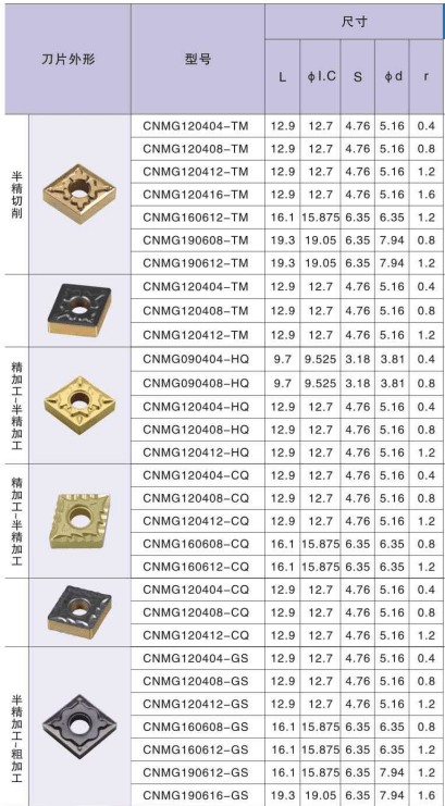
In steel turning applications, the Huana series has been shown to be an effective option for maintaining process security while maximizing tool life. The series now contains new chipbreakers for its negative insert lines, with styles TM, MA, HQ, and PM for cutting. These Chipbreakers are intended to further improve the grades’ performance across a wide variety of application areas.
In contrast, ceramics are prized for their high-temperature stability and chemical resistance, but they can be brittle and prone to chipping under certain conditions. Carbide inserts strike a balance between hardness, toughness, and thermal resistance, making them a preferred choice for a wide range of machining tasks. Their versatility, combined with their ability to maintain sharp cutting edges and endure challenging machining environments, positions carbide inserts as indispensable tools in modern manufacturing processes.
There are several reliable methods for effectively identifying carbide inserts, ensuring accurate selection and optimal performance.
Additionally, discussing common applications and maintenance tips enhances the article’s value, offering readers practical insights into maximizing the utility and lifespan of carbide inserts. The outline follows a logical flow, starting with foundational knowledge and gradually delving into more specific details. This structure ensures that readers can easily follow along and grasp the information presented.
Carbide inserts boast a diverse range of physical characteristics that are finely tuned to optimize machining performance. Firstly, these inserts come in a variety of shapes and sizes tailored to specific cutting tasks. Common shapes include square, triangular, round, and parallelogram, each designed to address different machining requirements and geometries. Triangular inserts, for instance, are ideal for general turning operations, while square inserts excel in facing and shoulder milling. Round inserts are often used for profiling and contouring, showcasing the adaptability of carbide inserts to various machining scenarios.
The ability of the CNMG inserts chip-breaker to block the heat from the chip from entering the insert was yet another benefit offered by this component. When using an insert with a flat top, the hot chip would glide over the face of the insert, and the heat from the chip would be transmitted into the insert, which would limit the life of the tool.
You should choose the insert grade (coatings) depending on the kind of material that is being cut, the exact machining operation that is being performed (finishing, medium, or roughing), and the cutting circumstances (smooth, lightly interrupted, heavily interrupted). The insert grade and the chip breaker work together to produce certain performance qualities, which are complemented by one another. A grade that is more wear resistant may give longer tool life on a cutting edge that is already strong, while a grade that is harder can compensate for a cutting edge that already has less strength.
The PM style is a flexible chipbreaker for medium cutting that incorporates an improved cutting edge and chip pocket profile to provide excellent chip control across a broad parameter range. This type of chipbreaker is designated by the designation PM.
On the other hand, the ANSI insert designation system, commonly used in North America, focuses on a numerical code for insert shape and size. While less detailed than the ISO system, the ANSI system is straightforward and easily understood, simplifying insert selection for those familiar with its conventions.
When it comes to selecting the appropriate turning insert, finding the insert that is most suited to the task at hand is just half the fight. The last step consists of choosing the most appropriate grade and chip breaker.
Visual Inspection: Visual inspection involves a comprehensive assessment of the insert’s physical attributes. Begin by examining the insert’s shape, as carbide inserts come in various geometries like square, triangular, or round. Compare the insert’s form with known carbide insert shapes to determine compatibility. Additionally, pay attention to color-coded markings that often indicate specific insert types or grades. These markings can provide valuable insights into the insert’s intended use. Detailed examination of the insert’s surface can also reveal any unique features or symbols that further aid in identification.
Moreover, symbols may be engraved on carbide inserts to provide additional insights into their capabilities. Symbols indicating chip breaker design, recommended cutting direction, and tolerance levels can help machinists make informed decisions when choosing inserts for specific machining operations.
This outline provides a comprehensive guide to identifying carbide inserts, catering to readers with varying levels of familiarity with the subject. By including detailed steps for visual identification, measurements, and magnetism tests, readers can confidently determine whether an insert is made of carbide. The outline also addresses the importance of insert markings and their interpretation, which is crucial for proper usage.
The act of turning, which is part of the machining process, involves a cutting tool called a bit that travels in a linear fashion while the workpiece rotates. The choice of CNMG 432 turning insert is highly influenced by the type of material being worked with. It is of the utmost importance to select a turning material of an appropriate grade, such as hardened steel. It requires insert grades that are exceptionally durable and stiff.
What sets carbide inserts apart from other cutting tool materials, such as high-speed steel (HSS) or ceramics, is their remarkable hardness and resistance to heat and wear. While HSS tools may exhibit good cutting performance, carbide inserts excel in demanding applications where high cutting speeds, heavy loads, and abrasive materials are encountered. The hardness of carbide ensures prolonged tool life and minimal edge deformation, contributing to consistent and precise machining results. Moreover, carbide inserts have the advantage of retaining their cutting edge at elevated temperatures, making them well-suited for high-speed and high-temperature cutting operations.
The top selection The CNMG120404 has greatly increased levels of wear resistance, heat resistance, and hardness, hence widening the application range significantly. There is a need for increased heat resistance in both CNMG120408 and CNMG120404. When machining is performed under controlled circumstances, it enables a fast-cutting speed as well as lengthy durations in cut.
By employing these identification techniques—visual inspection, measurements, and a magnetism test—machinists can confidently and accurately differentiate carbide inserts from other materials. This proficiency in identification ensures that the right insert is selected for the intended application, contributing to efficient and successful machining outcomes.
In addition to shapes and sizes, a color-coding system is often employed for insert identification. Different manufacturers may use distinct color schemes to indicate insert types, grades, and intended applications. This system streamlines the selection process and helps machinists quickly identify the most suitable insert for a specific machining task, enhancing operational efficiency and accuracy.

The first chip-breakers worked by curling the chip and applying pressure to cause it to shatter. This was their principal purpose. However, the “G” type chip-breakers were the only ones that were available. For example, CNMG, etc.
In the following paragraphs, we will explain how to go about picking the most appropriate CNMG insert shape and grade for the particular duties you have.
The performance of the next generation turning insert, model number CNMG120408, is superior in every manner. They are suggested for continuous as well as interrupted cuts since they are coated with technology that is of the second generation and have a wide variety of uses.
When finishing aluminum, it provides a surface finish that is of excellent quality. A chipbreaker that has been optimized offers improved chip control.
In conclusion, as a result of the development of modern technology, the HUANA CNMG turning inserts have also changed from the traditional welding turning tools to the machine-clamp turning inserts, as well as the CNMG 642 turning insert for standard CNC blades that are commonly used these days; The increasing popularity of high-speed CNMG Inserts has improved production efficiency, ensured the precision of cutting, and extended the service life of the blades.
The MA style chipbreaker, which was developed for finish turning, features a large inclination angle on the cutting edge and a newly designed chipbreaker that together offer improved chip control during machining at light depths of cut. These characteristics were included in the design of the chipbreaker. Because of its one-of-a-kind geometric design, it is able to provide a long and predictable tool life while preventing crater wear from accumulating on the rake face. This is particularly useful when machining at greater feed rates, which yields thicker chips.
It is feasible to optimize machining conditions, minimize machining time, increase machining efficiency, assure the quality of the workpiece that is being machined, and prolong the service life of the tool by making a reasonable selection of CNMG 432 insert geometry. Choose the appropriate angle for the CNMG insert based on the kind of tool you are using.
Huana has added TM, MA, HQ, and PM type chipbreakers to its best CNMG insert for stainless steel, making it the next generation of turning inserts available.
Magnetism Test: Conducting a magnetism test is another effective method for differentiating carbide inserts. Tungsten carbide, the primary component of carbide inserts, is not magnetic. To perform the test, bring a magnet close to the insert’s surface. If the insert is attracted to the magnet, it likely contains a significant amount of steel and is not a pure carbide insert. Conversely, if the insert exhibits little to no attraction, it is likely composed of carbide material.
Insert shape, geometry, grade, and other factors are only some of the numerous factors that should be considered when selecting the appropriate insert for your turning operations. The objective is to find an insert that satisfies your needs for both quality and performance while also delivering effective chip control and a level of wear resistance and tensile strength that is commensurate with industry standards.
Carbide inserts are often adorned with markings, codes, and symbols that convey essential information about their specifications and intended uses. Understanding these markings is crucial for selecting and utilizing carbide inserts effectively. Firstly, these markings typically include alphanumeric codes that denote key characteristics such as insert type, geometry, and cutting parameters. Deciphering these codes allows machinists to quickly identify the insert’s application range and compatibility.
Carbide inserts’ physical characteristics encompass a spectrum of shapes, sizes, color codes, and chip breaker designs. These aspects collectively empower machinists with the versatility and precision needed to achieve optimal results across a wide range of machining applications.
Insert style The characteristics of the portion and the depth of cut that you want to achieve should guide your decision about the insert style (shape and size). Larger nose radii are stronger, but they need more machine power and increase the likelihood that they may vibrate. A lower nose radius allows for more access to fine component details, but it results in a cutting edge that is less robust.
Determine the kind of chipbreaker (geometry) to use depending on the type of machining operation you will be performing: finishing, medium, or roughing. When roughing with high depths of cut and feedrates, the insert you use must have a cutting edge that is more durable.
Insert makers separate themselves from one another by making use of their own unique chip breakers. The labels were removed from turning inserts, and instead, generic breakers with the new chip-breaker names were added to the description, such as best CNMG insert for stainless steel.
Measurements: Precise measurements are crucial in distinguishing carbide inserts accurately. Utilize calipers or micrometers to measure key dimensions such as the insert’s length, width, and thickness. Compare these measurements to standard specifications provided by manufacturers or industry guidelines. Carbide inserts often have specific dimensions that differentiate them from other materials. Careful measurement ensures that the insert’s size aligns with the intended application.
With chip-breakers, a tiny “single bump” or groove would limit the amount of contact the chip had with the insert. As a result, the amount of heat passed into the insert would be reduced, which would lengthen the life of the tool. There was a significant gap in performance brought on by seemingly little variations in chip-breakers.
In comparison to conventional CNMG inserts, HUANA’s newly developed CNMG 642 inserts each have an angle that is less acute. When facing turning the wall, the additional space on the cutting edge allows for improved chip flow and reduces the likelihood of chip re-cutting difficulties occurring. A decreased nose angle also helps to reduce cutting force, which helps to reduce unpredictability in tool failure as well as chatter during the machining process. The new inserts come in a variety of chipbreaker types, including as TM, MA, HQ, and PM type chipbreakers, which may be used for finish turning as well as general purpose applications. Inserts from CNMG are available in the newest generation of grades, which are designed for use in steel turning for high temperature alloys.
When it comes to the extensive assortment of CMNG turning inserts and chipbreakers that HUANA has to offer, everything is feasible. We created each of these solutions, which include CMNG inserts of varying forms, sizes, and thicknesses, with the same objective in mind: to increase the productivity and tool life in your turning applications. This extensive selection, which encompasses all material groups, makes it possible for you to accomplish your objectives in terms of the rates of material removal, the tool life, and the surface quality.
Finishing processes that have shallow depths of cut and slower feedrates provide less cutting force, which means that cutting-edge strength is not as significant in these situations. Medium turning operations demand a more adaptable geometry since they have a wider variety of depths of cut and feedrates to accommodate.
During the profile turning or face turning processes, chip jamming and re-cutting can be a common challenge when the cutting is performed in the direction away from the work centre in one continuous path. This is because conventional CNMG 642 or DNMG turning inserts are made of a material called CNMG, which is a form of DNMG.
CNMG inserts are used extensively across a variety of processing equipment, including but not limited to machining centers, boring head holders, tool holders, and others. In the meanwhile, HUANA CNMG inserts have been added in order to facilitate the rapid rotation of the blade. CNMG 190612 inserts have a robust structure, which enables them to function at a higher level and last for a longer period of time in service. HUANA is the place to go if you want to acquire best CNMG insert for stainless steel at a price that is within your budget. Given the variety of deals that are now being offered, it is our mission to make it easier for you to take advantage of as many of the savings as is humanly feasible. At HUANA, you may kick your feet up and take it easy as you browse. Our objective is to simplify and expedite the steps involved in making an online purchase as much as is humanly practicable.
Another critical aspect is the design of chip breakers on carbide inserts. Chip breakers are strategically engineered features along the cutting edge that help control chip formation and evacuation during machining. These designs play a vital role in preventing chip entanglement, reducing heat generation, and enhancing chip disposal. Chip breakers vary in shape and placement, with options like straight, curved, and wavy configurations. The choice of chip breaker design depends on factors such as material type, cutting depth, and feed rate. For instance, a deep and robust chip breaker may be utilized for heavy roughing, while a finer chip breaker is preferred for finishing operations. The careful selection of chip breakers ensures improved chip control, reduced tool wear, and enhanced surface finish, highlighting the precision engineering inherent in carbide insert design.
In the not-too-distant past, inserts did not have chip breakers. If both the component and the set-up had flat tops, then any and all inserts would function. This resulted in a great deal of problems with chips that were inflexible, despite the fact that the machine had sufficient horse control. Turning presented a unique challenge since, in many instances, power was limited and the material did not have a “sticky” quality; as a result, turning was a continuous process that produced chips that were lengthy and stringy.
Milling, on the other hand, was termed an interrupted cut, and the chips produced were shorter than those produced by turning since the insert only cut for half a revolution during milling. Turning inserts were the natural starting point for the development of chip-breakers in cutting tools.
Always keep an eye out for CNMG grades that have the capacity to handle high temperatures and a significant amount of force while cutting, as this will allow you to identify items with exceptional durability. When stainless steel is turned, there is typically significant friction and heat generated as a result of the process. Because of this, it is extremely important to choose turning grades that are able to endure heat and give a long and robust life. Turning grades that are very productive can survive the high temperatures generated by turning these materials without suffering any edge loss.
Carbide inserts are essential components in modern machining processes, known for their exceptional durability and precision. These inserts are predominantly composed of tungsten carbide, a composite material formed by combining tungsten (a heavy, dense metal) with carbon. The resulting tungsten carbide is extremely hard and wear-resistant, making it ideal for cutting and shaping various materials. This composite is often combined with a binder material, such as cobalt, which enhances toughness and helps hold the tungsten carbide grains together.
Looking for CNMG insert? CNMG inserts that may be used in the cutting of a variety of materials, including wood, metal, and others. Drilling, milling, and turning are just some of the CNC techniques that this material is compatible with. Both the CNMG 190612 insert and the CNC tool lathe make use of this component. In the meanwhile, it is suitable for use with computer numerical control (CNC) machine machines, machining centers, and other similar devices. The primary body of the CNMG 642 is made out of steel, and the blade has a longer service life than similar products on the market. CNMG turning inserts are used as the principal component materials due to their respective high levels of hardness, high strength, strong toughness, exceptional toughness, and long service lives. At this moment, it is suitable for use with CNC lathes, milling machines, and drilling machines.
Understanding these markings and designation systems empowers machinists to make informed decisions when selecting carbide inserts, ensuring compatibility with their machining tasks and materials. This knowledge enhances operational efficiency and precision, underscoring the importance of accurate interpretation in optimizing machining outcomes.
To bring further clarity, carbide inserts adhere to international standards for designation, with two prominent systems being ISO (International Organization for Standardization) and ANSI (American National Standards Institute). The ISO system employs a standardized alphanumeric code that encapsulates insert geometry, cutting edge properties, and cutting direction. This comprehensive code aids in universal insert identification across different manufacturers and regions.


 18581906093