
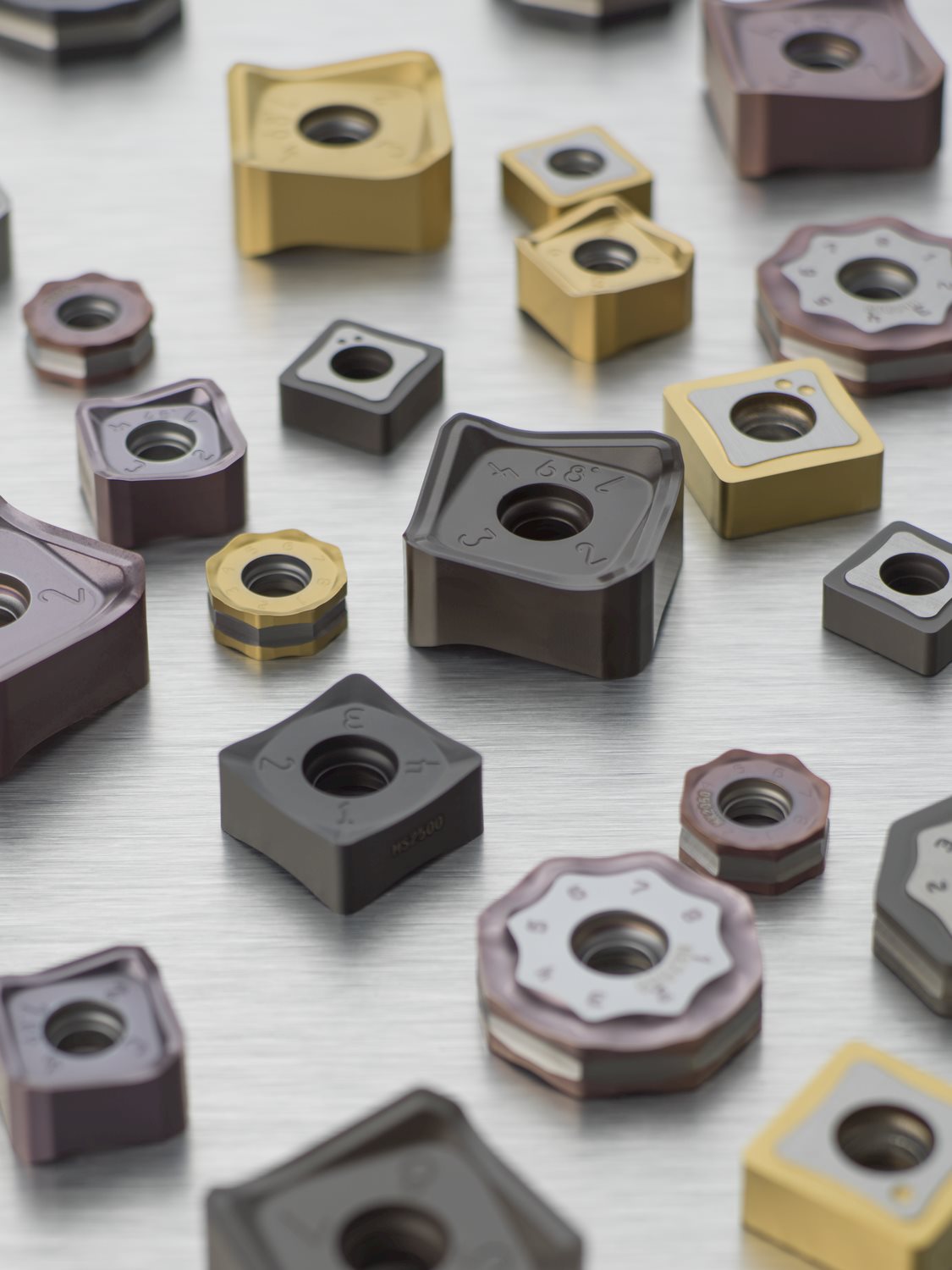
Insert geometries Mitsubishi - cnc lathe insert
The D geometry provides the highest edge protection with low rake angles for a strong cutting wedge angle. Applications in hard steels, high tensile stress steels or materials with extremely hard inclusions such as cast iron require stable cutting edges that withstand high dynamic mechanical loads without easily breaking. D geometry is also suitable when facing extreme vibrations that cannot be reduced or avoided by changing the cutting parameters to a more suitable working range. D geometry can generate high cutting forces and temperatures and may need to be optimized to M or MD geometries for lighter cutting and reduced vibrations in particular applications.

M indicates “medium” geometries. They are often an excellent first choice and used in many applications due to their versatility when it comes to material, cutting and wear behavior. Mid-level vibrations, heterogenous workpiece conditions as inclusions or raw skin, medium to higher tensile stress materials as well as moderate feed rates can be machined with this geometry type. M geometries are a strong go-to choice for the core materials of steels, cast iron and stainless steels.
The ME and MD geometries can be an optimization of the M geometry, depending on the identified wear pattern or machining behavior.
In addition to grade, the insert geometry has a tremendous impact on the machining process and the way the grade behaves and wears. A hard grade combined with a geometry that is too sharp can easily chip and fracture when performing extreme interrupted cuts or inclusions.
Conversely, extreme thermal and abrasive conditions will adversely impact tool life on an insert with a tough grade and heavily protected geometry. Optimizing your tool life and application is always a balance between insert grade and geometry.
A bridge geometry between E and M, ME provides the lighter cutting action and chip formation of an M geometry with less risk of edge chipping and breakage than with an E geometry. It is used more as an optimization of the M geometry than the E geometry because of its macro-geometry design. In comparison to the M geometry, ME has a higher rake angle and a smaller or more positive protection chamfer. This design is ideal for reducing cutting forces, chip thicknesses and built-up edges on low- to medium-alloyed steels, softer stainless steels and superalloy materials.
In addition to grade, the insert geometry has a tremendous impact on the machining process and the way the grade behaves and wears. A hard grade combined with a geometry that is too sharp can easily chip and fracture when performing extreme interrupted cuts or inclusions.Conversely, extreme thermal and abrasive conditions will adversely impact tool life on an insert with a tough grade and heavily protected geometry. Optimizing your tool life and application is always a balance between insert grade and geometry.The Seco geometry naming convention provides guidance as to how geometry affects the insert’s cutting action. M = Medium (e.g. XOMX120408TR-M12 MP2501)M indicates “medium” geometries. They are often an excellent first choice and used in many applications due to their versatility when it comes to material, cutting and wear behavior. Mid-level vibrations, heterogenous workpiece conditions as inclusions or raw skin, medium to higher tensile stress materials as well as moderate feed rates can be machined with this geometry type. M geometries are a strong go-to choice for the core materials of steels, cast iron and stainless steels.The ME and MD geometries can be an optimization of the M geometry, depending on the identified wear pattern or machining behavior.ME geometry: to reduce cutting forces or built-up edgesMD geometry: to reduce edge chipping or breakageFor more information about ME and MD geometries, see below. ME = Medium – Easy (e.g. XOMX120408TR-ME08 T350M)A bridge geometry between E and M, ME provides the lighter cutting action and chip formation of an M geometry with less risk of edge chipping and breakage than with an E geometry. It is used more as an optimization of the M geometry than the E geometry because of its macro-geometry design. In comparison to the M geometry, ME has a higher rake angle and a smaller or more positive protection chamfer. This design is ideal for reducing cutting forces, chip thicknesses and built-up edges on low- to medium-alloyed steels, softer stainless steels and superalloy materials. MD = Medium – Difficult (e.g. XOMX120408TR-MD13 MP1501)To reduce edge chipping or breakage under the higher mechanical loads of high tensile stress materials, high feed rates under stable cutting conditions or cutting edge chipping due to vibrations or inclusions, the MD geometry uses a more negative protected cutting edge than M geometry but provides lighter cutting in comparison to a D geometry. MD geometry is typically used for tough or high-performance cast iron roughing applications, medium to higher alloyed steels and hardened steels. E = Easy (e.g. XOEX120408FR-E06 H15)E stands for “easy” cutting and is perfect for low-strength materials such as non-ferrous metals or low-alloyed steels and stainless steels. The geometry is sharp without any protection chamfer and has a high rake angle to reduce cutting forces and plastic deformation during chip formation. This geometry is suitable for all metals that deform easily and tend to cause built-up edges. Typically, uncoated or PVD-coated grades are offered in this combination to keep the sharp characteristic of this geometry, since thicker CVD coatings are too brittle and too thick to stick to these sharp cutting edges. D = Difficult (e.g. XOMX120408TR-D14 MK1500)The D geometry provides the highest edge protection with low rake angles for a strong cutting wedge angle. Applications in hard steels, high tensile stress steels or materials with extremely hard inclusions such as cast iron require stable cutting edges that withstand high dynamic mechanical loads without easily breaking. D geometry is also suitable when facing extreme vibrations that cannot be reduced or avoided by changing the cutting parameters to a more suitable working range. D geometry can generate high cutting forces and temperatures and may need to be optimized to M or MD geometries for lighter cutting and reduced vibrations in particular applications.
E stands for “easy” cutting and is perfect for low-strength materials such as non-ferrous metals or low-alloyed steels and stainless steels. The geometry is sharp without any protection chamfer and has a high rake angle to reduce cutting forces and plastic deformation during chip formation. This geometry is suitable for all metals that deform easily and tend to cause built-up edges. Typically, uncoated or PVD-coated grades are offered in this combination to keep the sharp characteristic of this geometry, since thicker CVD coatings are too brittle and too thick to stick to these sharp cutting edges.
To reduce edge chipping or breakage under the higher mechanical loads of high tensile stress materials, high feed rates under stable cutting conditions or cutting edge chipping due to vibrations or inclusions, the MD geometry uses a more negative protected cutting edge than M geometry but provides lighter cutting in comparison to a D geometry. MD geometry is typically used for tough or high-performance cast iron roughing applications, medium to higher alloyed steels and hardened steels.


 18581906093