
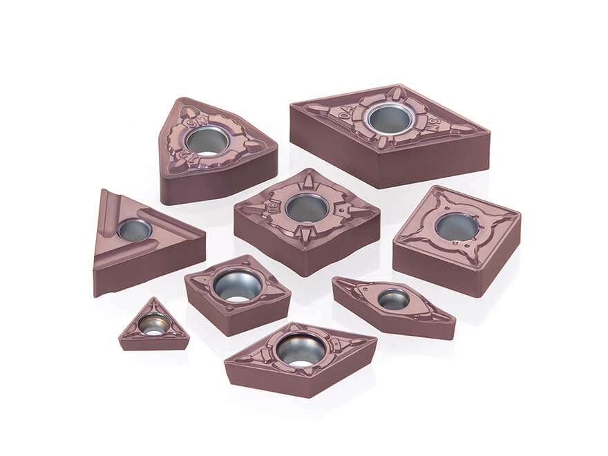
Insert milling cutter - insert cutter milling
PVD coatings are used for most of the grooving and parting operations for a number of reasons. Since PVD coatings are thinner and adhere to sharp cutting edges better, the cutting edges can be sharper than with a typical CVD coated tool. The advantage is that the cutting edge generates lower forces, which in turn create less heat, and therefore less wear; and along with a very smooth surface, PVD coatings are less susceptible to built-up edge that is common in stainless steels and high temperature alloys. The sharper edge also significantly reduces the tool pressure that leads to work hardening of those alloys susceptible to it.
A. Without a chip breaker, there really aren’t any good ways to control the chips, and turn-grooving would be extremely difficult. The only option is to use a peck cycle to stop the cutting process and clear the chip. But that reduces productivity, and the chips are still quite long and cause problems. The chip breakers developed for grooving over the last 20 years have been a tremendous improvement to the grooving process.
For most coating systems there is a trade-off between the higher wear resistance of CVD coatings containing aluminum oxide and PVD coatings that do not. With the Walter Tiger·tec® Silver PVD technology, the best of both worlds is provided – sharp edges and smooth coatings along with the superior heat and wear resistance of aluminum oxide. By providing all these advantages together, the insert has a wider application range, simplifying application for the customer while providing excellent performance.
A. It is quite important to select feed rate and speed that is appropriate for the workpiece material. This ensures the best performance of the insert, and the best possible productivity.
The outer layer consists of a high Ti-content nano-structured multilayer made possible by Tungaloy’s latest coating technology. Its high hardness and nano structure provides the grade with a good balance of wear and fracture resistance, enhancing tool life and predictability.
Walter AG is one of the world's leading metalworking companies. As provider of specialized machining solutions, Walter offers a wide range of precision tools for milling, turning, drilling and threading applications. Walter works together with its customers to develop custom solutions for fully machining components for use in the aviation and aerospace industries, as well as automotive, energy, and general engineering. The company demonstrates its Engineering Kompetenz at every stage of the machining process. As an innovative partner capable of creating digital process solutions for optimal efficiency, Walter is pioneering Industry 4.0 throughout the machining industry.
Signing into Better MRO is easy. Use your MSCdirect.com username / password, or register to create an account. We’ll bring you back here as soon as you’re done.
Due to its high fracture and deformation resistance, the cutting edge is perfectly capable to sustain interrupted cuts, as well as continuous cuts, but most importantly eliminates turning inconsistencies that could potentially cause Built-Up-Edge formation.
A chip breaking mechanism is super important especially while machining Stainless steel due to the nature of the workpiece material ductility. When machining stainless steel, it is complicated to bend, deflect and finally break the newly formed chip. The difficulty of breaking the chip imposes other concerns, some of them related to damaging the fresh surface of the part that was just machined, and by that affecting the product quality, and others are more focused on preventing the swirls of removed metal from clogging the cavity space inside the CNC lathe machine.
The outstanding combination of specially designed substrate and advanced PVD coating, along with vast geometries and parameters such as large selection of chip breakers, corner radiuses and positive and negative rake angles, makes Tungaloy’s grade AH6225 the perfect solution for turning stainless steel parts.
A general rule for all grooving operations is to choose the widest insert possible that will do the job. This provides the strongest insert to handle the widely varying forces during the various phases of the cut, and the insert also has more mass to handle the heat generated especially at the bottom of the groove.
A. For most situations, a chip breaker geometry is very useful. The only materials that don’t need chip breaker geometry are cast irons since the material naturally forms only small chips. The chip breaker folds the chip so that its width is less than the width of the groove – important to minimize contact of the chip with the walls of the groove so they can be ejected easily. This contraction of the chip prevents scratching of the groove walls to maintain a good surface finish.
A. Bad things. Depending on how far the cutting parameters are from the recommended values, there can be a wide range of effects. At the very least the tool life will be reduced. Improper parameters can also lead to chipping of the cutting edge, severe chip control problems, poor surface finish, and other issues; at its worst it can cause insert fracture and damage to the workpiece and the toolholder.
Thanks to high thermal conductivity of the substrate, heat generated during machining is dissipated, efficiently reducing temperature on the cutting edge. This provides edge toughness, while reducing plastic deformation of the cutting edge. Ideal for continuous cuts.
TUNGALOY AUSTRALIA PTY LTD Unit 68 1470 Ferntree Gully Road, Knoxfield 3180 Victoria, Australia Phone: +61-3-9755-8147 Fax: +61-3-9755-6070 CONTACT FORM >
A. The multi-functional chip breaker has a form that varies around the insert cutting edge. The geometry on the front edge is designed for optimum chip form in radial operations and provides short, tight chips that are easily evacuated even when cutting low carbon steels like 1018. The chip breaker geometry on the sides of the insert comes into play during the axial turning phase of groove turning. Because the forces and material flow are different than in radial operations, the edge geometry and position of the chip breaking elements need to be different to get proper chip control. Finally, the corners of the insert are also different in form so that the insert leaves a good surface finish during axial turning operations.
A. As with most turning applications, tool choice for grooving operations depends on the details. For radial grooving operations, tool choice is straightforward. The toolholder needs to have the proper depth of cut capability to complete the groove, and securely clamp the insert. Choosing the toolholder with the shortest cutting depth that will do the job is best because the rigidity of the tool has an influence on tool life of the insert. The more rigidity and clamping force on the insert, the longer it will last. Insert choice depends on the workpiece material and the cycle time requirements. By having the appropriate geometry for the operation, the chip will be controlled and will easily exit the groove. Radial grooving operations can be done very effectively with either short single edge inserts, or with the longer two-edge inserts.
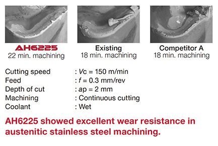
Tungaloy recently launched a revolutionised grade AH6225, which is undoubtably the best carbide grade in the market for turning Austenitic stainless steel. AH6225 combines specially designed Tungsten Carbide substrate with advanced PVD high Ti-content nano multilayered coating technology.
For groove-turning operations, the rigidity of the toolholder is even more important since the forces during groove turning are at 90° to the tool’s strength. So again, using a tool holder with the shortest cutting depth that will do the job is best. For groove turning the insert of choice is the longer two-edge style since the longer inserts are better able to resist the side forces generated in the turning operation. The geometry of the groove turning insert is also critical: it needs to have very good chip control properties in both the radial and axial cutting directions. Inserts for groove turning are designed with the proper chip breaker form around all the cutting edges, although that form may vary significantly from the front of the insert to the sides to handle the different flow of the chip in axial and radial grooving.
The journey to remove any machining barriers or issues of inconsistency related to turning Austenitic stainless steel parts always starts by contacting one of the local representative experts of Tungaloy in your country. With such a large selection of metalworking solutions such as geometries, clamping mechanism, positive/negative geometries and chip breakers all designed by Tungaloy’s engineers, one of Tungaloy’s experts could certainly find the best match that will ensure an optimal solution to your needs.
When turning stainless steel parts with AH6225 grade, the smooth reliable machining operation with predictable surface finish and tool life, not only makes the job more manageable and reliable, but also increase productivity beyond expectation, allowing the tool to operate at a versatile range of operations, including interrupted and continuous cut at high feed rates and cutting speed of 100-150 meters per minute.
A. The coating provides heat and wear resistance to the tool, and provides a barrier to the highly reactive chips that can quickly wear away unprotected carbide. By keeping the heat away from the core of the insert, it prevents deformation of the cutting edge that creates higher forces and ultimately insert failure.
A. The cutting edge geometry determines the shearing action during the metal cutting process, as well as the strength of the cutting edge. A sharp and positive cutting edge will shear the workpiece material with low cutting pressure, and as a result generate less heat and also have less tendency for work hardening of the workpiece material. The trade-off is that the sharp edge is more susceptible to chipping from interruptions in the cut or higher feed rates. A stronger and more negative cutting edge geometry will better withstand higher forces and interruptions, but the price is higher cutting pressures, more heat generated, and a higher likelihood of work hardening.
Another significant factor is the higher toughness of PVD coated tools. This becomes quite important for parting operations that cut to the center of a solid bar. As the insert cuts to center, keeping the cutting speed constant requires higher rpm on the spindle. The maximum rpm for the machine is reached, and at that point the cutting speed drops quickly, eventually reaching zero at the center. The slower speeds generate high forces on the cutting edge, making it more susceptible to chipping. By using tougher PVD coated inserts, edge reliability is improved significantly.
What makes the process of machining stainless steel parts so difficult is the alloy composition of the workpiece material that normally exhibits high strength and good plasticity. Therefore, during the machining process an excessive amount of heat is generated around the vicinity of the cut and dissipated into the workpiece material. The result is a work hardening effect which ultimately makes the workpiece much harder, and what we see is a rapidly faster tool wear which develops along the cutting edge.
Turning Austenitic stainless steel hold a great deal of challenges, including Built-Up-Edge, inaccurate dimensions, scratches on the surface and unpredictable tool life. Tungaloy, as a market leader in metalworking, has been seeking an ultimate solution to resolve these issues.
The engineeringly designed substrate provides resistance to plastic deformation that could impact the cutting edge and an advanced PVD coating technology that protects the cutting edge and ensures long and predictable tool life due to its high hardness and superior fracture and wear resistance. With all these powerful features, Tungaloy’s grade AH6225 is also available with a vast range of uniquely designed chip breakers, superimposed on negative and positive type geometries, pressed together and honed using a unique edge preparation technology owned by Tungaloy that makes these turning inserts super special.
A. Work hardening occurs during metal cutting due to the deformation of the workpiece material below the cutting edge of the insert. Use an insert with a relatively sharp edge preparation so the cutting edge creates as little pressure as possible. Ensure that the feed rate is larger than the minimum recommended for the insert geometry and width.


 18581906093