
Kennametal Grade Descriptions - carbide milling insert chart
Choose the chip breaker (geometry) based on the selected machining operation: finishing, medium, or roughing. Roughing with high depths of cut and feedrates requires an insert with a stronger cutting edge.
For external machining and facing. The large point angle is very rigid, and good for rough machining. This is the most commonly used insert.
HMU – Medium Universal A medium universal geometry with a soft cutting action due to its positive geometry. Has a versatile application range, and is suited for turning unstable components and for boring applications.
Choose the insert grade (coatings) based on the type of material being cut, the specific machining operation (finishing, medium, roughing), and the cutting conditions (smooth, lightly interrupted, heavily interrupted). The insert grade and the chip breaker complement each other to provide specific performance characteristics. A tougher grade can compensate for a cutting edge with less strength, while a more wear resistant grade can provide longer tool life on a stronger cutting edge.
For internal machining. The 60° cutting angle provides medium cutting-edge strength that allows for both ID roughing and finishing applications.
HMR – Light to Medium Roughing For light to medium roughing of steels, difficult-to-machine high-alloy titanium, and aluminum materials. High strength to deal with heavy chip deformation.
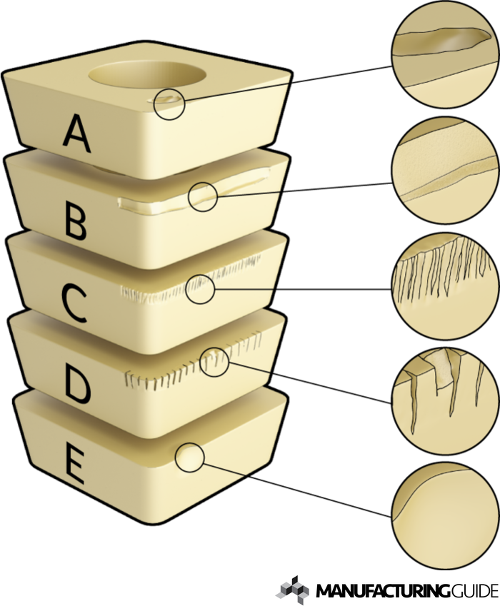
The cause of tool wear can be divided into the following types, that individually or in combination, will inevitably require a tool change.
HUF – Ultra-Fine Finishing For finishing, with a positive cutting edge for reduced cutting forces and superior surface quality.
HFF – Fine Finishing For finish turning, producing smooth, accurate surfaces. Very good chip control, especially at low depths of cut
HUM – Universal Medium For medium-duty turning operations. Soft-cutting chip breaker. Used in applications producing varying chip sections, such as profile or copy turning. Good dimensional accuracy. For soft steel materials and stainless steels.
The smaller point angle of this insert is more versatile for finishing and detail work, but it has less cutting-edge strength than other geometries.
Choose the insert style (shape and size) based on the features of the part and the desired depth of cut. A larger nose radius is stronger, but requires more machine power, and increases the tendency for vibration. A smaller nose radius increases the access to fine part features, but has a weaker cutting edge.
HMS – Medium High-Temp For medium machining in high-temp materials. Utilizes a micro-finished edge preparation to increase edge toughness.
D. Comb cracks Small cracks across the edge. Caused by repeated thermal changes that cause the material to expand and contract, which leads to cracks and subsequent chipping.
HUR – Universal Roughing Roughing geometry, with smooth chip forming and improved coolant flow for increased tool life. Positive geometry reduces cutting forces, and improves depth-of-cut notching resistance. Ideally suited for stainless steel applications, and for smooth machining of steel.
CCET – Finishing Positive (Single-Sided) For finishing turning operations, with optimal chip control over a wide range of cutting conditions and workpiece materials.
HFS – Finishing High-Temp For finishing applications. Ground periphery with positive cutting edge. Ideally suited for high-temp alloys. Micro-finished edge on the ground periphery adds just a slight hone for improved edge integrity and reliability.
There are many variables that go into choosing the correct insert for your turning operations: insert shape, geometry, grade, and more. The goal is to select an insert that meets your requirements for quality and performance, while providing good chip control, and a reasonable combination of wear resistance and toughness.
E. Plastic deformation Deformation at the edge. Caused by weakening of the cutting tool due to overheating, which reduces its resistance to external impact.
HRH – Roughing Heavy For medium-duty to roughing. Outstanding chip control. High edge strength for interrupted cuts, forging skin, or scale. Preferred for all cast iron, such as gray, malleable, and nodular.
The smaller point angle of this insert is more versatile for finishing and detail work, but it has less cutting-edge strength than other geometries.
C. Notch wear Streaked wear on the bottom of the edge. Caused by mechanical abrasion from harder workpieces which, in the same way as crater wear, occurs due to hard particle diffusion. If a larger notch occurs among the smaller ones, it is probably due to the surface deformation from a previous cuttin pass. The notches can also appear on the rake side of the insert.
This insert has 3 cutting edges per side. The 80° cutting angle provides high cutting-edge strength for roughing, but the depth of cut is limited by the short cutting edge.
This price includes shipping cost, export and import duties, insurance, and any other expenses incurred during shipping to a location in France agreed with you as a buyer. No other mandatory costs can be added to the delivery of a Haas CNC Product.
HFP – Finishing Positive (Single-Sided) For finishing to medium turning operations, with optimal chip control over a wide range of cutting conditions and workpiece materials.
HMP – Medium Positive (Single-Sided) For medium to rough turning, with reduced cutting forces and improved chip control for high feedrates. Suitable for high metal removal rates.
A. Crater wear Crater-shaped wear on the cutting edge of the insert. Caused by mechanical abrasion when hard particles in the chip, eg oxides or carbides, meet the cutting surface. Diffusion between the material and the insert accelerates the formation of the crater wear.
Finishing operations with light depths of cut and lower feedrates produce lower cutting forces, so cutting-edge strength is not as important. Medium turning operations, with a wide range of depths of cut and feedrate, require a more versatile geometry.
B. Flank wear Smooth wear on the flank of the insert. Caused by mechanical abrasion which, similar to crater wear, occurs due to wear from hard particles.
Cutting tool wear The edge of a cutting tool wears down during machining which impairs the ability to achieve the desired tolerances and consistent quality.
Cutting forces The wear is strongly associated with the cutting forces that a cutting insert is subjected to, which are a result of the tool's design, the angle of the tool holder, the cutting speeds, the choice of material, vibrations etc. Actual cutting forces are thus impossible calculate.


 18581906093