
Kennametal Grade Descriptions - iso carbide insert grade chart
Truck mounted water well drilling rig.WDP-300 Water Well Drilling Rig for water well drilling. It can be used for mud circulation Show More...
Product DescriptionLUHAI MWD system is equipped with international brand of directional sensor and gamma sensor, use US patented w Show More...

Beton-tech company IntroductionBeton Technology is a well-known and professional PCB manufacturer, located in ShenZhen,GuangDong P Show More...
In the lesson we saw three examples of ISO nomenclature when we asked Paolo the question; we saw an RNMG, a WNMG and a WCGT. Apart from the first letter which distinguishes the form, the first two inserts have identical parameters 2, 3 and 4 and exactly _NMG. This is also the most common ISO nomenclature for double-sided tools with chipbreaker geometry; these, as we shall see in the lesson on side rake angles, are fitted to negative tools. While the third case of the exercise posed to Paolo has parameters 2, 3 and 4 equal, _CGT. The latter is the most common ISO nomenclature for single-sided inserts.
Good morning, in today’s additional info I would like to give you some examples of ISO nomenclature in order to help you become familiar with the names of the inserts but above all with the coding itself. It is very important for anyone working in machining to know and understand the insert and its ISO nomenclature.
Again, this is an uncommon insert but ideal for understanding the ISO nomenclature. It is a screw-clamp type insert with a countersunk slot, used in finishing or semi-finishing operations on internal machining tools such as boring bars. Sometimes for some builders it is also used in drilling on mechanically clamped drills.
Specifications & size? HDF-1Technical parameters? Power supply?220Vu00b15% 50Hz Power?1.2KW Speed adjustment ranging?0-800 r min A Show More...
The last parameter to be considered is the pair of letters which in this case is PF. The field n°12 is left empty by the ISO standard for the insert builder who uses it to indicate the geometry of the chipbreaker drawn on the insert face. This geometry is fundamental for a correct use of the insert.
The second letter determines the value of the insert clearance angle. N for the ISO is an angle of 0 degrees so our insert can be a double-sided insert, so it can be used on both sides. It should also be noted at this point that the fixing of the insert on the tool is of the lever type and therefore a strong fixing.
Product Name: Oil Drilling Grade Carboxy Methyl lose(CMC)Product Description:CMC appears to be white or light yellow powder, Show More...
To be precise in turning operations, it is measured in mm per revolution, i.e. the distance covered by the tip of the insert at each turn of the workpiece. The values, as we shall see, range from a few hundredths of a millimetre to a few millimetres in the rarest cases. A small nose radius implies small feeds; large nose radius allows large feeds to be used.
In fact, each geometry has been designed and studied to control chip formation in precise applications. These applications vary in terms of material groups and type of machining: finishing, medium removal or roughing. In our case we have used the letters PF as an example, where P identifies the family of steels while F indicates the finishing operation. So in this case the chipbreaker geometry is suitable for finishing operations on steels.
As we said in the lesson, the first letter identifies the shape of the insert; in this case is triangular with an angle between the cutting edges of 60 degrees.
DFT PCD indexable drilling inserts and tool holderswe supply tool holders with DFT pcd inserts1.Features:1) high hardness,2) good Show More...
The length of the cutting edge will influence the removal capacity of the insert depending on the thickness. This thickness is determined by the second pair of numbers, which we see here as 04. This pair indicates a thickness of 4.76 mm from the inch-millimetre conversion. Other cutting edge lengths will have different thicknesses.
1.Hole diameter:90mm-1200mm;2.Hole depth:300m;3.Drill head lifting force:105kN;4.Main hoist lifting force:20.6kN;5.Support power: Show More...
SINOSUN Group is one of China's dominant water well drill rig manufacture and exporters. Water well drilling rig and drilling rig Show More...
Kalium Humic Acid appears as black powder. It is easily soluble in water, and formsions hydrate base with negative charge, and hav Show More...
Water well drilling tube carbon steel Straight In ern Perforated Metal Pipe: Product Description API K55 J55 Standard Per Show More...
LUHAI MWD system is equipped with international brand of directional sensor and gamma sensor, use US patented well depth measureme Show More...
Name: PAM ACAS No.: 9003-05-8Key words or Synonyms:Polyacrylamide, PAM, AMolecular formula: (C3H5NO)nGrade: Industrial Grade Show More...

eWorldTrade.com provides 1077 products, Manufacturers and Suppliers from China, Germany, Indonesia, Japan, Kenya and Nigeria. . You have multiple options to select like Steel, plastics, Plastic + rubber + metal and metal. Process duration from 15 to 5 Days. You can get Sheetrock Drill in bulk quantity. The Sheetrock Drill can be shipped from Fedex, Qingdao, Istanbul, Birmingham, Port of Montreal, DHL, Worldwide and shanghai. Payment options are T/T, L/C, D/A, D/P, Western Union, Money Gram and PayPal.
-BZT300SZ trailer mounted water well drilling rig can be pulled by tractor and other motor tractor, so it is convenient to move.-T Show More...
Please note that thickness is very important as it constitutes the resistant section of the cutting edge. The greater the thickness, the greater the strength of our insert. Sometimes, in order to increase the life of the cutting edge with the same chip volume, i.e. with the same working data, it is sufficient to oversize the length of the cutting edge. This will provide a higher thickness, which will guarantee high resistance to the cutting forces and temperatures that will develop during turning.
13.5" Disc Blade assembly with 204 series bearing, 3.5mm (0.138) thick. Dust cover and bolt included.for Great Plains Grain Drills Show More...
To conclude, we can say that knowing the insert nomenclature you will have identified every dimensional and constructional aspect of your insert. Only the geometry of the chip breaker will be excluded from ISO, since it is not included in the standard and is defined differently from builder to builder.
The industrial hose pump is a new, multifunction and multipurpose industrial pump developed on the basis of foreign advanced techn Show More...
The third and last pair of numbers in this part is 04, which in tenths of a millimetre is the value of the nose radius. The nose radius influences the strength of the cutting edge. In fact, a radius such as in this case 0.4 mm cannot be used for heavy roughing operations where, on the contrary, a larger radius will be useful, for example 1.2 mm. Therefore, this value of 0.4 mm also means that the field of application for this insert will be finishing or other light operations.
All Offers/Products/Company Profiles/Images and other user-posted contents are posted by the user and eWorldTrade.com shall not be detained accountable for any such content.
Our factory can supply variety Diamond Drill ( PCD Drill). Diamond PCD layer 2-4mm, Total Thickness is 8mm-15mm, Diameter is 1mm-1 Show More...
Good morning, in today’s additional info I would like to give you some examples of ISO nomenclature in order to help you become familiar with the names of the inserts but above all with the coding itself. It is very important for anyone working in machining to know and understand the insert and its ISO nomenclature. In the lesson we saw three examples of ISO nomenclature when we asked Paolo the question; we saw an RNMG, a WNMG and a WCGT. Apart from the first letter which distinguishes the form, the first two inserts have identical parameters 2, 3 and 4 and exactly _NMG. This is also the most common ISO nomenclature for double-sided tools with chipbreaker geometry; these, as we shall see in the lesson on side rake angles, are fitted to negative tools. While the third case of the exercise posed to Paolo has parameters 2, 3 and 4 equal, _CGT. The latter is the most common ISO nomenclature for single-sided inserts. Let’s look at a new case very similar to the one seen in the lesson. TNMG 160404 PF So let’s go in order and start with the letter T. Insert shape As we said in the lesson, the first letter identifies the shape of the insert; in this case is triangular with an angle between the cutting edges of 60 degrees. Side rake angle The second letter determines the value of the insert clearance angle. N for the ISO is an angle of 0 degrees so our insert can be a double-sided insert, so it can be used on both sides. It should also be noted at this point that the fixing of the insert on the tool is of the lever type and therefore a strong fixing. Tolerance Then we come to the third letter M. M establishes the tolerance class that is given with respect to the circle inscribed in the geometric figure of the insert. In this case is a circle with a diameter of 9.525. This value, the diameter of the inscribed circle, is taken from the insert size table, which we will see with parameter 5 relating to the size. Class M is a tolerance that is not very precise but nevertheless one of the most widely used in turning and which corresponds exactly to ±0.05 mm. Insert type Let’s now move on to G, the last letter of the alphanumeric code; it indicates that our insert has a chip-breaking geometry on the face of the cutting edge, suitable for controlling and breaking the chips that will be formed during machining. Obviously, the geometry is studied and carried out on both faces of the insert. Moreover it has some characteristics in relation to the material to be machined and the operation to be carried out, i.e. finishing or roughing of a component. After the letters we now move on to the numbers, which as we have seen are taken in pairs. Size The first pair equals to 16 mm: this is the length of the insert side. With the triangular shape there are also other lengths, for example 11 or 22mm. The side dimension is 16 mm, which corresponds to an inscribed circle of 9.525 mm. This number was used to calculate the numerical value of tolerance M. Thickness The length of the cutting edge will influence the removal capacity of the insert depending on the thickness. This thickness is determined by the second pair of numbers, which we see here as 04. This pair indicates a thickness of 4.76 mm from the inch-millimetre conversion. Other cutting edge lengths will have different thicknesses. Please note that thickness is very important as it constitutes the resistant section of the cutting edge. The greater the thickness, the greater the strength of our insert. Sometimes, in order to increase the life of the cutting edge with the same chip volume, i.e. with the same working data, it is sufficient to oversize the length of the cutting edge. This will provide a higher thickness, which will guarantee high resistance to the cutting forces and temperatures that will develop during turning. Nose radius The third and last pair of numbers in this part is 04, which in tenths of a millimetre is the value of the nose radius. The nose radius influences the strength of the cutting edge. In fact, a radius such as in this case 0.4 mm cannot be used for heavy roughing operations where, on the contrary, a larger radius will be useful, for example 1.2 mm. Therefore, this value of 0.4 mm also means that the field of application for this insert will be finishing or other light operations. The last parameter to be considered is the pair of letters which in this case is PF. The field n°12 is left empty by the ISO standard for the insert builder who uses it to indicate the geometry of the chipbreaker drawn on the insert face. This geometry is fundamental for a correct use of the insert. In fact, each geometry has been designed and studied to control chip formation in precise applications. These applications vary in terms of material groups and type of machining: finishing, medium removal or roughing. In our case we have used the letters PF as an example, where P identifies the family of steels while F indicates the finishing operation. So in this case the chipbreaker geometry is suitable for finishing operations on steels. To conclude, we can say that knowing the insert nomenclature you will have identified every dimensional and constructional aspect of your insert. Only the geometry of the chip breaker will be excluded from ISO, since it is not included in the standard and is defined differently from builder to builder. TPGN 110308 This second example of an insert is not very common, but it is shown here for educational purposes. It is a turning and finishing insert that is assembled on boring bars for internal machining or on adjustable boring cartridges. The insert has a flat face and its fixing system is of the micro-fused bracket type. T = triangular-shaped insert P = 11 degree insert clearance angle G = tolerance class in this case of accuracy N = insert with a flat face without chipbreaker geometry 11 in millimetres is the length of the side of the insert 03 indicates the thickness S of the product, here set at 3.17 millimetres 08 in tenths of a millimetre is the value of the nose radius which in this case is 0.8mm SOEX 120508 Again, this is an uncommon insert but ideal for understanding the ISO nomenclature. It is a screw-clamp type insert with a countersunk slot, used in finishing or semi-finishing operations on internal machining tools such as boring bars. Sometimes for some builders it is also used in drilling on mechanically clamped drills. S = square-shaped insert O = 8 degree insert clearance angle E = tolerance class on inscribed circle. Precision insert (inscribed circle equal to mm 12,70) X = special non ISO standard (this letter only) with chipbreaker geometry 12 = in mm insert side length mm 12 05 = thickness value, in this case is 5.16mm 08 = in tenths of a millimetre the value of the nose radius, in this case 0.8mm CHOICE OF NOSE RADIUS Now that we have seen some examples of coding that have been more or less used, let’s say a few words about the choice of the insert nose radius. The nose radius influences a very important cutting data, the feed rate. We will dedicate a specific lesson to the feed rate, but for the moment let’s say that it identifies the speed at which the tool carries out its removal path. To be precise in turning operations, it is measured in mm per revolution, i.e. the distance covered by the tip of the insert at each turn of the workpiece. The values, as we shall see, range from a few hundredths of a millimetre to a few millimetres in the rarest cases. A small nose radius implies small feeds; large nose radius allows large feeds to be used. When choosing the radius of the point we must take into account various aspects which I will list below: In finishing operations the nose radius influences the internal corner radius that will remain on the workpiece profile. So it is usually the design or construction guidelines of the workpiece that define the maximum insert corner radius. Usually the most commonly used radius that takes this into account is 0.4mm. Obviously, if your workpiece has no internal corner radius or the value of the internal radius left on the workpiece is irrelevant, the choice of insert radius will be made on the basis of the following considerations; Larger nose radius, stronger inserts; With large nose radius, high feed rates are possible (more on this in the feed rate lesson); Adopting large nose radius (all other cutting parameters being equal) will develop more radial forces, which are one of the primary sources of vibration. This last aspect is the one that puts a limit on the maximum nose radius that can be used. We will return to this subject in future lessons.
Introduction of Oil Drilling CMCShandong Taihe Group (Hongkong) Co., Ltd"THCMC"Introduction to Oil Drilling CMC,"THCMC" CMC oilfie Show More...
Kalium Humic Acid KHM appears as black powder. It is easily soluble in water, and forms ions hydrate base with negative charge, an Show More...
CMC can be used as water-soluble gel for frilling fluids, and can form aresian well liquor.u00b2 It has good water-loss controllin Show More...
This second example of an insert is not very common, but it is shown here for educational purposes. It is a turning and finishing insert that is assembled on boring bars for internal machining or on adjustable boring cartridges. The insert has a flat face and its fixing system is of the micro-fused bracket type.
Product Description1)Diameter: M3.5,M4.2,M4.8,M5.5,M6.32) Length: 13mm-125mmProduct Feature3)Surface:White Nickel, Black Nickel, W Show More...
The nose radius influences a very important cutting data, the feed rate. We will dedicate a specific lesson to the feed rate, but for the moment let’s say that it identifies the speed at which the tool carries out its removal path.
Now that we have seen some examples of coding that have been more or less used, let’s say a few words about the choice of the insert nose radius.
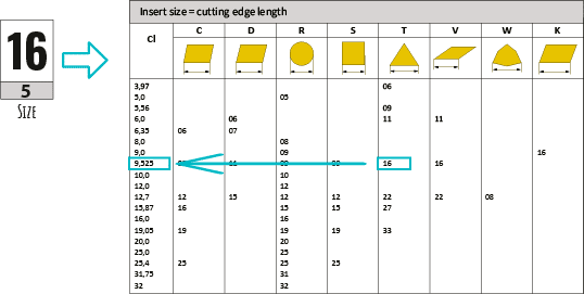
Then we come to the third letter M. M establishes the tolerance class that is given with respect to the circle inscribed in the geometric figure of the insert. In this case is a circle with a diameter of 9.525. This value, the diameter of the inscribed circle, is taken from the insert size table, which we will see with parameter 5 relating to the size. Class M is a tolerance that is not very precise but nevertheless one of the most widely used in turning and which corresponds exactly to ±0.05 mm.
The first pair equals to 16 mm: this is the length of the insert side. With the triangular shape there are also other lengths, for example 11 or 22mm. The side dimension is 16 mm, which corresponds to an inscribed circle of 9.525 mm. This number was used to calculate the numerical value of tolerance M.
Let’s now move on to G, the last letter of the alphanumeric code; it indicates that our insert has a chip-breaking geometry on the face of the cutting edge, suitable for controlling and breaking the chips that will be formed during machining. Obviously, the geometry is studied and carried out on both faces of the insert. Moreover it has some characteristics in relation to the material to be machined and the operation to be carried out, i.e. finishing or roughing of a component.


 18581906093