
Ceratizit tackles milling of HRSA materials with new ceramic inserts - carbide insert grades
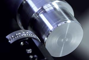
MAPAL recently announced a milling range with pressed, radial ISO indexable inserts. The milling cutter for roughing the face surface on the turbocharger housing comes from this range. The ISO indexable inserts with 16 usable cutting edges are the highlight of this facemilling cutter. As such the usage of the tool is particularly economical.
Most turbochargers are exhaust gas turbochargers. These look different at almost every automotive manufacturer and have a special geometry. Common to all: there are very high temperatures when they are used in vehicles with petrol engines. For this reason the turbine housing, the so-called “hot side” is manufactured from very abrasive, heat-resistant materials. These materials represent a particular challenge for every machining tool.
“We have seen as little as a 30 per cent in cycle times and a high end of 80 per cent reduction,” said Ball. “In the upper range, the cycle time reduction also takes into account a reduction in rest roughing and semifinishing.”
Replaceable tool that clamps into a tool body, drill, mill or other cutter body designed to accommodate inserts. Most inserts are made of cemented carbide. Often they are coated with a hard material. Other insert materials are ceramic, cermet, polycrystalline cubic boron nitride and polycrystalline diamond. The insert is used until dull, then indexed, or turned, to expose a fresh cutting edge. When the entire insert is dull, it is usually discarded. Some inserts can be resharpened.
Material: 1.4837 | Cooling: MQL | Diameter: 119 mm | Cutting speed: 80 m/min | Feed: 0.3 mm | Tool life: 100 parts
“Niagara Cutter [a division of Seco] has a multiflute family of tools that is used for this type of cutting. They feature a 38-degree helix, large core diameters, and multiple flutes (6, 7, 9). The tools used for optimized roughing typically have some sort of corner protection (radius or chamfer) and are coated to provide both heat and abrasion resistance, typically an AlTiN coating,” said Bell.
When it comes to the overall manufacturing process, optimized roughing can typically remove 90 to 95 per cent of the rough stock on a workpiece. This leaves only about 1 to 2 per cent of the tool diameter as finish stock for removal.
AE-VMS short series endmills designed for stable milling application, ideal for wide range of material like Carbon steel, Alloy steel and Stainless steel to Titanium alloys and Ni alloys.
2. Understand the power of CAM. It is impossible to program an optimized roughing strategy manually. You need to use a programming software package that will control the cutting strategy. But not just any programming software will work; it needs to be the right software for this application. A program designed only for high-speed side milling will not perform optimized roughing.
Material: 1.4849 | Cooling: Dry machining | Diameter: 125 mm, 14 inserts | Cutting speed: 80 m/min | Feed: 0.12 mm | Tool life: 125 parts
Any controlled equipment that allows an operator to program its movement by entering a series of coded numbers and symbols. See CNC, computer numerical control; DNC, direct numerical control.
“There might be some additional corner picking that you need to get closer to near net shape before you can move on to finishing, but this strategy takes the bulk of the material out,” said Ball.
“Today’s CAM software can be programmed to create an optimized roughing stage that uses a large DOC and light radial engagement to maximize metal removal rates. It’s a type of milling operation that is very well suited to pocketing and side profiling,” said Jay Ball, product manager for solid-carbide end mills – NAFTA at Seco Tools.
Workpiece is held in a chuck, mounted on a face plate or secured between centers and rotated while a cutting tool, normally a single-point tool, is fed into it along its periphery or across its end or face. Takes the form of straight turning (cutting along the periphery of the workpiece); taper turning (creating a taper); step turning (turning different-size diameters on the same work); chamfering (beveling an edge or shoulder); facing (cutting on an end); turning threads (usually external but can be internal); roughing (high-volume metal removal); and finishing (final light cuts). Performed on lathes, turning centers, chucking machines, automatic screw machines and similar machines.
Optimized roughing uses a large DOC and light radial engagement to maximize metal removal rates. Photo courtesy of Seco Tools.
The best use of the optimized roughing technique is in situations that can use the full flute length of the tool, such as roughing long, straight walls. Photo courtesy of Seco Tools.
The turbocharger has been state-of-the-art in diesel vehicles for some time. And almost all automotive manufacturers offer a turbocharged petrol engine. Why? The turbocharger makes comparable performance with a smaller engine capacity possible and that contributes to the advance in downsizing. Turbochargers also help to achieve lower fuel consumption and are therefore fundamental in meeting strict emission limits. MAPAL offers the complete process for machining these parts, including tools.
An award-winning writer and graduate of the Sheridan College journalism program, he has published articles worldwide in a variety of industries, including manufacturing, pharmaceutical, medical, infrastructure, and entertainment.
As the number of flutes increases, the stepover must decrease to maintain surface finish at faster feed rates. If the stepover is too large, feed rates must be lowered, and more heat is generated with the larger amount of metal removed in each pass. By decreasing the stepover, faster cutting speeds can be achieved. This requires more passes, but the metal removal rates are still higher than at slower speeds because of the increased feed rates.
Easily access valuable industry resources now with full access to the digital edition of Canadian Fabricating & Welding.
The holder needs to provide less than 0.0004 in. of runout. A precise holder ensures the accuracy of the process, whereas a less secure holder will cause undesirable levels of vibration at optimized roughing’s high feed rates.
For the optimized roughing operation to be successful, a constant radial DOC must be maintained. This radial DOC also depends on the material being cut. For example, superalloys can have a radial DOC that is 5 to 7 per cent of the tool diameter, while tool steel under 50 HRC can use 7 to 10 per cent of the tool’s diameter as the radial DOC value.
“Instead of encasing the tool in 180 degrees of engagement, which creates a lot of heat and a lot of pressure, better metal removal rates are achieved with optimized roughing because machinists can take a 2xD DOC and use a 10 to 12 per cent stepover, depending on material. This means you generate less heat and have less radial engagement, which means you can accelerate feed rate and surface footage rate. This is what reduces cycle time,” he added.
Today’s advanced optimized roughing is only effective if implemented properly. And while similar in nature to other strategies, optimized roughing entails specific best practices that shops must adhere to and common missteps they must avoid to achieve optimum results.
Optimized roughing improves metal removal rates (Q), reduces the amount of time spent in the roughing phase, and increases tool life, all while reducing the load on the machine, according to Ball.
Loosely, any milling tool. Horizontal cutters take the form of plain milling cutters, plain spiral-tooth cutters, helical cutters, side-milling cutters, staggered-tooth side-milling cutters, facemilling cutters, angular cutters, double-angle cutters, convex and concave form-milling cutters, straddle-sprocket cutters, spur-gear cutters, corner-rounding cutters and slitting saws. Vertical cutters use shank-mounted cutting tools, including endmills, T-slot cutters, Woodruff keyseat cutters and dovetail cutters; these may also be used on horizontal mills. See milling.
Machining operation in which metal or other material is removed by applying power to a rotating cutter. In vertical milling, the cutting tool is mounted vertically on the spindle. In horizontal milling, the cutting tool is mounted horizontally, either directly on the spindle or on an arbor. Horizontal milling is further broken down into conventional milling, where the cutter rotates opposite the direction of feed, or “up” into the workpiece; and climb milling, where the cutter rotates in the direction of feed, or “down” into the workpiece. Milling operations include plane or surface milling, endmilling, facemilling, angle milling, form milling and profiling.
The four tools mentioned demonstrate, on the one hand, the different machining tasks on a turbocharger and, on the other hand, symbolise the variety of tools and know-how available from MAPAL. From standard milling cutters, through mechatronic actuating tools, to complex boring tools, the programme includes all the tools necessary for machining turbochargers, including the tool clamping systems. MAPAL designs the complete machining process such that the most reliable and cost-effective strategy for the customer is used. There is always a close eye on accuracy down to the μm so that the turbochargers achieve the highest possible efficiency in operation.
Overall cycle time is dependent on the part. If a part is near-net forged, for example, it will not require as much roughing as a solid block will. Another example is a mould cavity: It requires much more time to be spent in the finishing stage rather than the roughing stage because a smooth 3-D finish is required.
A particular challenge during the machining of the turbine housing for exhaust gas turbochargers is the main turbine bore. Its manufacture is subject to close tolerances in relation to shape, position and surface finish. The bore is bell-mouthed shaped to generate the best possible flow characteristics. MAPAL undertakes this machining operation using TOOLTRONIC with the LAT attachment (linear actuating tool). TOOLTRONIC, a mechatronic tool system, is a full NC axis integrated into the existing machine controller. The mounting tool is fitted with three inserts, one for roughing and two for finishing.
Optimized roughing is not for every part; it’s very component driven. If a part is a complex, 3-D component, optimized roughing is not going to be the most efficient way to get the highest metal removal rate during the roughing stage. When it can be employed, however, it can have a significant effect on cycle times.
The amount of stepover that can be used depends on tool diameter and the number of flutes on the tool. For example, a 6-flute, 0.5-in. end mill cutting 4140 steel can use a 10 to 12 per cent stepover. With a 7-flute tool, the stepover is only 8 per cent. Moving to a 9-flute tool reduces the stepover to roughly 3 per cent.
Joe Thompson has been covering the Canadian manufacturing sector for more than two decades. He is responsible for the day-to-day editorial direction of the magazine, providing a uniquely Canadian look at the world of metal manufacturing.
Form of milling that produces a flat surface generally at right angles to the rotating axis of a cutter having teeth or inserts both on its periphery and on its end face.
Enlarging a hole that already has been drilled or cored. Generally, it is an operation of truing the previously drilled hole with a single-point, lathe-type tool. Boring is essentially internal turning, in that usually a single-point cutting tool forms the internal shape. Some tools are available with two cutting edges to balance cutting forces.
Rigid workholding also is important to minimize vibration in the part or, in the worst-case scenario, movement of the workpiece.
Easily access valuable industry resources now with full access to the digital edition of Canadian Metalworking.
Substance used for grinding, honing, lapping, superfinishing and polishing. Examples include garnet, emery, corundum, silicon carbide, cubic boron nitride and diamond in various grit sizes.
A large part of turbocharger machining can be implemented using tools with ISO indexable inserts. Including many machining processes on the challenging hot side. MAPAL has developed a cutting material specially matched to the machining of heat-resistant cast steel and that offers long tool lives and therefore high cost-effectiveness, despite the abrasiveness of the material.
According to Ball, the best use of optimized roughing is in situations that use the full flute length of the tool. Roughing long, straight walls is a good example of this.
The number of flutes determines the stepover percentage because it determines the chip spacing. Tool diameter also plays a role. For example, a 0.5-in.-dia. tool with 9 flutes has less chip spacing than a 1-in.-dia. tool with 9 flutes.
Material: 1.4837| Cooling: MQL | Diameter: 49; 70.5; 73; 90 mm; chamfer 10° | Cutting speed: 70 m/min | Feed: 0.4 mm | Tool life: 75 parts
MAPAL has taken up these challenges and developed new cutting materials and tools. The company offers the complete process for machining turbochargers, including all tools, for example, drills, milling cutters, reamers and mechatronic actuating tools – matched to the related geometry of the turbocharger. The company also assists its customers during the continuous further development of processes, to reduce cycle times and to increase tool lives. As such, combination tools that undertake multiple machining operations in one machining step form part of the portfolio.
1. Use the right machine. Machines used for optimized roughing need two things: fast spindles and rigidity. The spindles must generate the necessary revolutions per minute for optimized roughing’s feed rates. The rigidity of the machine minimizes vibration and contributes to part quality.
The new tool from MAPAL for pre-machining the catalytic converter flange is also particularly cost-effective. Tangential technology is used on this diameter turning tool. Due to the upright and horizontal installation of the LTHU inserts, in effect eight cutting edges can be used per indexable insert.
4. Use the tooling manufacturer’s recommended cutting parameters. Do not rely on the default cutting speed and feed rate data from programming software suppliers. Cutting tool suppliers develop the recommended cutting parameters after research and through years of experience. Tool makers optimize cutting data for the tool’s design and specifications and for the material group you are working with.
Endless band, normally with serrated teeth, that serves as the cutting tool for cutoff or contour band machines.
3. Don’t cut too deep. A cutting depth of 2xD that takes the full length of the cut in one pass is recommended. The shallow radial stepover enables the depth of the cut. A larger stepover would require a shallower depth of cut to achieve the same metal removal rates. However, a cut that is too deep, more than 3xD for example, creates cutting pressures greater than the tool can bear and causes deflection.
It is necessary to machine the V band on every turbocharger. Along with the material properties, an interrupted cut is often a challenge here during pre-machining. MAPAL relies on a complex boring tool with ISO indexable inserts to pre-machine the V band as well as to pre-machine the internal contour of the turbine. The tool therefore machines internally and externally simultaneously. Multiple steps are machined. The tool operates counterclockwise to transport the chips out of the component and to prevent damage to the internal contour of the turbine.
CNC machine tool capable of drilling, reaming, tapping, milling and boring. Normally comes with an automatic toolchanger. See automatic toolchanger.
During the roughing phase, the vast majority of material is removed from the part, typically leaving only what is required for the finishing phase.
Keep up to date with the latest news, events, and technology for all things metal from our pair of monthly magazines written specifically for Canadian manufacturers!
“With any solid-carbide application in which you are trying to hold tight tolerances, the holders can make you or break you,” said Ball. “If you try to run these strategies and these processes in a collet that is not rigid or doesn’t contain the runout, you will struggle to achieve the metal removal rate and cycle time reduction this strategy can provide.”
Material: 1.4837 | Cooling: MQL | Diameter: 40.5-57.295 mm | Cutting speed: 140 m/min (roughing), 120 m/min (finishing) | Feed: 0.15-0.4 mm | Tool life: 50 parts
Cutting tool repeatedly enters and exits the work. Subjects tool to shock loading, making tool toughness, impact strength and flexibility vital. Closely associated with milling operations. See shock loading.
Ball suggested milling chucks, shrink-fit holders, and high-precision collet chuck systems when using this milling strategy.


 18581906093