
Milling Indexable Inserts - indexable milling insert
The cutting-edge length of a milling insert is an important factor that directly affects the insert's cutting performance and efficiency.
The hand of a milling insert refers to the orientation or direction of the insert's cutting edge and its corresponding shape.
Therefore, selecting the appropriate cutting-edge length is crucial in achieving optimal cutting performance, maximising productivity, and ensuring cost-effective milling operations.
The relief angle for a milling insert is of paramount importance in achieving efficient and successful machining operations.
It determines whether the insert is designed for right-hand (clockwise) or left-hand (anti-clockwise) rotation during milling operations.
Whether you're a seasoned machinist looking to expand your knowledge or a newcomer to the world of milling seeking clarity, this guide is here to demystify the milling insert ISO code. We'll explore how this code provides vital information about the insert's geometry, material, and cutting characteristics. By the end, you'll be equipped with the knowledge to decode and interpret these codes, empowering you to select the perfect milling inserts to optimise your machining processes.
Additionally, tight tolerances enable interchangeability within a tooling system, minimising downtime. They also impact tool life and performance, as well as surface finish and accuracy.
The radius can also impact the insert's cutting forces, chip control, tool life, and surface finish. Careful consideration of the appropriate nose radius based on the specific machining requirements and materials is crucial for achieving optimal performance, tool longevity, and surface finish in milling operations.

Understanding the milling insert ISO code is like deciphering a secret language that holds the key to successful milling operations and tool selection.
The edge preparation of a milling insert refers to the intentional modification of the cutting edge before its use in machining operations. It involves applying specific treatments or coatings to enhance the insert's performance and durability.
Common cross-section types include square, round, triangle, rhombic, and pentagonal. Machinists should consider the cross-section type when selecting inserts to ensure optimal cutting capabilities and chip evacuation for their specific machining tasks and materials.
By unravelling the meanings behind each section, machinists can confidently select the appropriate milling inserts, ensuring compatibility with their machining setup and achieving desired outcomes in terms of performance, precision, and tool longevity.
The thickness of an insert is crucial for its strength and stability during the cutting process.A thicker insert excels under heavy loads, enhancing performance and minimizing the risk of cutting edge chipping.
The system is designed so that each important feature and dimension of the insert is shown using a code system. This becomes the name of the insert.
It begins with a letter that indicates the insert's shape, such as R for round, S for square, T for triangular, D for diamond-shaped, or C for rhombic.
The tolerance of a milling insert is important for several reasons. Firstly, it ensures a proper fit and compatibility with the toolholder, promoting stable and secure clamping during machining. Secondly, precise tolerances contribute to dimensional accuracy, allowing for consistent and reliable machining results.
It's important to remember that the ISO designation system is not a system that standardizes the quality of the insert. Neither the carbide grade nor the cutting geometry is standardized in this designation system.
Tolerance refers to the allowable variation in dimensions or measurements of a manufactured part. In the context of milling inserts, the tolerance class specified in section 3 of the ISO code helps determine the level of accuracy and consistency of the insert's dimensions.
Therefore, selecting the appropriate thickness is essential for achieving optimal cutting performance, productivity, and the desired quality of the machined components.
The cross-section type of a milling insert refers to the shape of its cutting edge when viewed from a perpendicular angle. It influences the insert's cutting action and performance.
Armed with this knowledge, you're ready to decode the milling insert ISO code and unlock the potential of your milling endeavours.
By carefully selecting and applying the appropriate edge preparation techniques, machinists can achieve improved machining performance, productivity, and tool longevity, while also maintaining high-quality surface finish and dimensional accuracy.
It plays a crucial role in chip formation, tool life, cutting forces, and surface finish. Understanding the influence of the relief angle and selecting the appropriate one can greatly enhance machining performance, productivity, and the quality of the finished product.
We continues to enhance our visibility and reputation, including exhibitions all over the world and we also actively taking corporate social responsibility.
If you've ever ventured into the world of milling, you've likely come across the term "ISO code" in reference to milling inserts. But what exactly does this code mean? What information does it convey? Understanding the milling insert ISO code is crucial for selecting the right tool for your milling operations and achieving optimal results.
The nose radius of a milling insert holds significant importance in achieving precise and efficient machining operations whilst being able to apply a radius to your cut. Smaller radius tend to be more suitable for finer cuts/finishing whilst larger radius are better for heavy metal removal due to the strength of the insert corner.
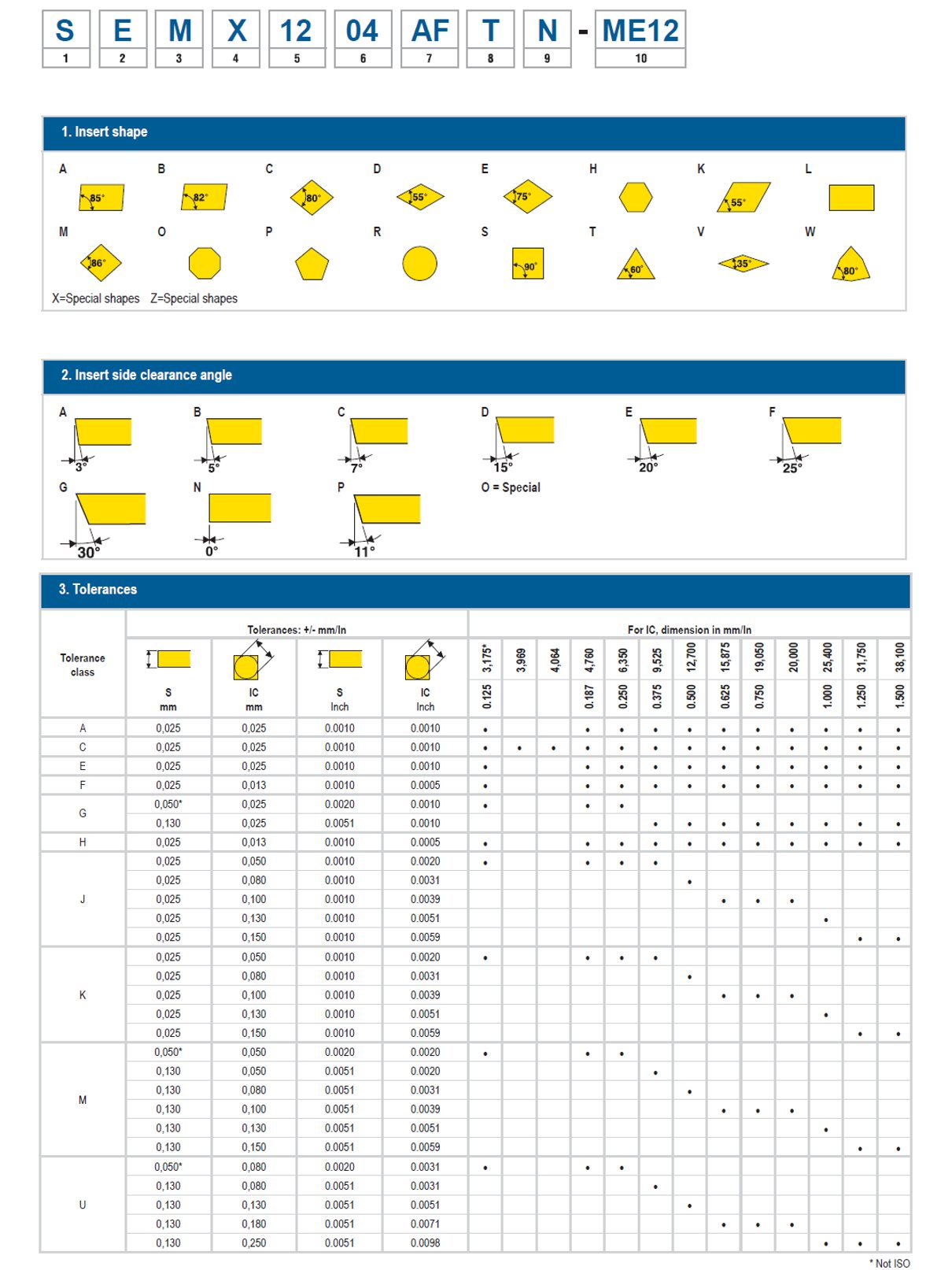
THE ISO designation system for indexable insertsThe ISO designation system for indexable inserts (ISO 1832) is a standardized system to name an indexable insert.The system is designed so that each important feature and dimension of the insert is shown using a code system. This becomes the name of the insert. This system has several advantages:Unique naming of an indexable insert (supplier independent)All important features and dimensions are clearly stated in the nameSome code positions relate to the insert carrier in which the insert can be mounted It's important to remember that the ISO designation system is not a system that standardizes the quality of the insert. Neither the carbide grade nor the cutting geometry is standardized in this designation system. This is an example for milling inserts. For other applications, you can refer to the relevant Machining Navigator. Do you want to know more?Contact Us Inline Content - SurveyCurrent code - 5fce8e61489f3034e74adc64
This letter gives a quick visual cue about the overall form of the insert. By looking at the first letter of the milling insert ISO code, machinists can get an initial understanding of the insert's shape, which plays a significant role in determining its specific applications and cutting capabilities.
A longer cutting-edge length allows for a larger contact area between the insert and the workpiece, resulting in increased productivity and improved material removal rates. It enables the insert to engage with a greater surface area of the material, reducing the number of passes required to complete a machining operation.
The chip breaker of a milling insert refers to a specially designed geometry on the insert's face and cutting edge that helps control and shape the formation of chips during the machining process.


 18581906093