
Straight to a round - grooving insert geometry
In some instances, he said, “a coated tool is only a few dollars more than an uncoated one. But in the right materials, it can give you three to five times the tool life of an uncoated tool. So you get a great return for a small investment in the tool.”
“The grades Iscar uses for our inserts depend on how fast the machine spindle can spin,” says Iscar Tool’s Geisel. “10,000 rpm sounds high but remember you are working with very small parts, around .100 in. in diameter. So that 10,000 rpm with a .100 in. diameter works out to be about 260 sfm…we need to design and produce the insert out of carbide grades with coatings that can run at such speeds.”
Another timesaving option he recommends is using a multigroove tool to cut multiple grooves right next to each other. To simultaneously cut four adjacent grooves, for example, shops can use an insert with four adjacent cutting edges.
If chamfers are on the top of the grooves, Coomer said the insert can be modified to create those features as well, “so you can cut all four grooves and put chamfers on them in one shot.”
When indexable tools are used for grooving, “many times your chipbreaker is a big key to success,” said Travis Coomer, national key account manager at GWS Tool Group in Tavares, Florida.
“The challenge with grooving is that below 1.5 mm it is difficult to make a tool that is strong enough,” says John Stewart, VP of engineering at Bokum Tool in Madison Heights, MI. “The overall determining factor is: What does a groove look like in a hole that size? If it is proportionally very similar to a larger hole then it is theoretically possible to get very small, but it really comes down to the strength of the tool itself.”
“As a tooling manufacturer, we are being pushed to produce tooling able to groove in smaller, and smaller diameters. Our PICCO line can produce grooves in diameters from as small as 2 mm (.08 in.) and we can go smaller by special request.”
Provided with a part drawing or the part itself, Mikron will grind a tool designed for the special form or profile to be grooved into the part.
Among the coatings that Scientific Cutting Tools uses for grooving tools are diamondlike carbon coatings, such as ta-C, which he describes as a very hard, thin coating that works well on tools used to cut abrasive nonferrous materials.
For deep grooving applications, the company typically produces solid-carbide tools because of their superior rigidity. White pointed out that the allowable length-to-diameter ratio for carbide tools is 10-1 compared with 3-1 for indexable toolholders made of steel.
Workpiece is held in a chuck, mounted on a face plate or secured between centers and rotated while a cutting tool, normally a single-point tool, is fed into it along its periphery or across its end or face. Takes the form of straight turning (cutting along the periphery of the workpiece); taper turning (creating a taper); step turning (turning different-size diameters on the same work); chamfering (beveling an edge or shoulder); facing (cutting on an end); turning threads (usually external but can be internal); roughing (high-volume metal removal); and finishing (final light cuts). Performed on lathes, turning centers, chucking machines, automatic screw machines and similar machines.
A single insert also can be used to combine grooving and turning processes. This wasn’t the case back when East worked at a machine shop.
“If you can’t get the chips out of the bore,” White said, “usually you will re-cut them, and then they will scar the surface.”
“There are companies that require face grooves with major diameters as small as 0.2 mm,” says Duane Drape, national sales manager for Horn USA Inc., in Franklin, TN. “This is mostly aluminium, but I have had customer requirements to get that small with steel at 50 + Rockwell.”
“If you are cutting to small major diameters on the face, where the grooves generally aren’t that deep, the chips are not an issue,” says Drape. “But in ID grooving applications where the groove is deep into a bore, then we need to get coolant in, and also need to break down the chip so it can evacuate.”
“The cutting process produces pressure on the work piece and on the tool. Controlling the pressure during machining dictates how successful we will be [in producing an effective cutting tool]. We can control cutting pressures by controlling the width of the grooving insert; the wider the insert, the more pressure it will produce. We also grind positive rakes on the inserts to control the pressure and to act as a chip former to control the chip shape and size.”
“When customers come to us for grooving tools, it is usually for a turnkey operation” — that is, a job for which Mikron produces most if not all of the different tools needed to make a part, said Sales Manager Nathan Lisker.
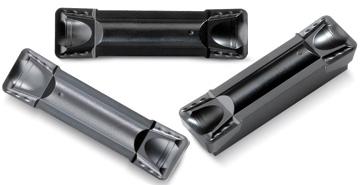
Coolant Ring Technology holders allow better coolant penetration into a bore during cutting operations. Image courtesy of Scientific Cutting Tools
When customers ask why they should pay more for Jet-Cut holders, he points out that coolant pinpointed on the cutting edge increases tool life, which translates into more parts per edge. He notes as well that efficiently delivered coolant quenches chips and makes them brittle, so they break up more easily.
East said groove/turn operations used to require two things. One was that CAD/CAM companies had to be pressed to create code for the work. Also, he said a special type of insert was needed, one with a chipformer on the front for plunging, plus a chipformer on each side for turning.
Easily access valuable industry resources now with full access to the digital edition of Canadian Fabricating & Welding.
As a result, Cogsdill’s tools are better suited to high production lines, an area that has seen some big changes of late. Only a few years ago, small bores were typically 4 mm, but now leading vendors are delivering off-the-shelf bore grooves to 2 mm, with specialty applications going much smaller. This has resulted in new abilities—and challenges—when it comes to grooving very small parts, as well as increased demand.
Grooving also goes better these days thanks to advances in tool coatings. The latest coating materials are heat- and wear-resistant, which increases tool life. White said they additionally improve speeds and feeds by preventing workpiece materials from sticking to tools.
“You need the chips to be able to freely get out of the bore and away from the cutting action so they do not interfere with the machining process.”
Hydraulics, given their need to control pressure, create demand for inside diameter (ID) and outside diameter (OD) grooving seals and threads, as well as relief grooves. In the automotive sector, miniature grooving applications include fittings for air bags and fuel injection components.
Substances having metallic properties and being composed of two or more chemical elements of which at least one is a metal.
Chip problems like these can be prevented by improved coolant delivery, which is possible today thanks to several developments. One is the increased coolant pressures produced by current machines. White said these pressures typically range from 300 psi all the way up to 1,000 psi.
Another approach is to compress chip width, thus ensuring it doesn’t lodge in the groove and result in tool failure. Either way, when it comes to grooving small parts, the combination of slow feed rates, proper tool selection, and a strategy for chip evacuation is the best way to ensure success.
William Leventon is a contributing editor to Cutting Tool Engineering magazine. Contact him by phone at 609-920-3335 or via email at wleventon@gmail.com.
“This is a double-sided insert that works well with slow cutting forces,” says Kaufmann. “The GUP insert geometry is advanced and versatile, with excellent metal removing rates.”
If the tool isn’t, “the edge of your tool is going to be tilted, so you could potentially be running scrap parts,” said Clay East, national product manager for grip systems at Iscar Metals Inc. in Arlington, Texas.
“These can be challenging if they are at the bottom of a small-diameter hole,” he said. “You’ve got to have the proper reach to get to the groove (location) and then be able to machine it successfully.”
“Even if the groove was wider than it was deep,” he said, “if it had 90-degree corners, you would take a groove tool and plunge all of that material out. Today, we want to apply a groove/turn solution in these cases.”
Turning machine capable of sawing, milling, grinding, gear-cutting, drilling, reaming, boring, threading, facing, chamfering, grooving, knurling, spinning, parting, necking, taper-cutting, and cam- and eccentric-cutting, as well as step- and straight-turning. Comes in a variety of forms, ranging from manual to semiautomatic to fully automatic, with major types being engine lathes, turning and contouring lathes, turret lathes and numerical-control lathes. The engine lathe consists of a headstock and spindle, tailstock, bed, carriage (complete with apron) and cross slides. Features include gear- (speed) and feed-selector levers, toolpost, compound rest, lead screw and reversing lead screw, threading dial and rapid-traverse lever. Special lathe types include through-the-spindle, camshaft and crankshaft, brake drum and rotor, spinning and gun-barrel machines. Toolroom and bench lathes are used for precision work; the former for tool-and-die work and similar tasks, the latter for small workpieces (instruments, watches), normally without a power feed. Models are typically designated according to their “swing,” or the largest-diameter workpiece that can be rotated; bed length, or the distance between centers; and horsepower generated. See turning machine.
Shops can get off to a good start with grooving by making sure the tool in the lathe turret is perpendicular to the workpiece surface.
“Exotic materials are not for production jobs—these are low volume applications,” says Tom Ficker, regional sales manager for Cogsdill Tool Products, Inc., with responsibility for Canada. “The problem with precision grooving in high nickel alloys is that you beat down on the grooving insert almost from the get-go.”
He recommends running an indicator along the length of the tool to check perpendicularity. For a 102 mm (4") tool length, the measurement should be off by no more than about 0.1 mm (0.004"), he said.
“Slow feeds can be a good idea, depending on the material,” says Bokum Tool’s Stewart. “With smaller sizes a weaker tool neck will want to deflect, especially with carbide, and with increased distance to the groove, feed speeds need to be adjusted downward.”
Common grooving options today include solid-carbide tools and indexables. When it comes to grooving, the focus at Scientific Cutting Tools Inc. in Simi Valley, California, is mainly on grinding solid-carbide tools for cutting internal grooves for things like threads and O-rings, said Sales Director Todd White.
“If (the tool) is going on a lathe, our message is to use coolant-through tooling as a first choice,” said East, whose company offers tooling products of this type called Jet-Cut.
If the groove to be cut isn’t too deep, he believes that Top Notch-style inserts may be a good choice. These feature molded notches on the top and bottom that seat the inserts in their holders. With the inserts held at a 3-degree angle, the notches pull them back into the pocket during cutting, he explained, making the system very rigid and stable.
If the chip created by the grooving tooth is wider than the finished groove, then you can minimize the possibility that the chip will stay in the groove. But when it comes to harder metals the challenge isn’t chip control so much as creating the chip in the first place. “At 1.5 mm you need to have a tool that is strong enough to create the chip,” says Stewart. “But from there, with a strong alloy like Inconel, it is relatively easy to control the chip. In the case of aluminium and softer materials, where the chip is continuous, it creates greater headaches because the material balls up.”
Substance used for grinding, honing, lapping, superfinishing and polishing. Examples include garnet, emery, corundum, silicon carbide, cubic boron nitride and diamond in various grit sizes.
“The geometries are not standardized, but there are ways to create space at the head of the tool to promote chip flow,” says Stewart. “Sometimes the actual grooving tooth on the cutting tool will have a chip breaker on it—this will help the chip move out and get flushed with coolant.”
But replaceable inserts, single edge, can still get to some small diameters. More cost effective than a solid carbide tool, they can also deliver better axial depth. That said, solid carbide tools are usually more expensive, toolholders aren’t, and there is a risk the holder might break after a dozen or so uses.
The problem with carbide is that reducing deflection increases the risk a tool will break, so it’s important to preserve the strength of the neck of the tool. Tool monitoring is also recommended, because with small cutting edges it can be hard to see or hear when a tool breaks.
He advises those who use inserts to cut grooves to make sure the chipbreaker folds the chip in a way that makes it smaller than the groove being cut.
Solid carbide grooving tools are usually L-shaped. Part of the challenge is that even the non-cutting, or “leg” part has to fit into the bore diameter. Given that the bottom of the L, or the “foot” has to be even smaller, strength becomes an issue, as does the fact that groove depth is limited. As a result, with bores of less than 2 mm in diameter the best tools are now constrained to a groove depth of around 0.2 mm.
A frequent issue is whether or not to go with inserts or solid carbide tools. Inserts can be indexable or have only one edge for single use. Inserts tend to be less expensive, but usually can’t get into the smallest bores, and are not as strong as solid-carbide tools.
Groove or other tool geometry that breaks chips into small fragments as they come off the workpiece. Designed to prevent chips from becoming so long that they are difficult to control, catch in turning parts and cause safety problems.
“It would be preferable to take an indexable insert into small grooves, because it would be more economical. But you often have to go with a one piece design, using a brace tool with a carbide or carbon steel cutter brazed to it.”
Managing chip generation in tight spaces has always been a challenge, because the smaller the hole the harder it is to get the chip out. One approach is to plum or port the tool to get coolant out. There are also advanced tools, like Kennametal’s AF-GUP insert geometry for grooving and turning, that are specially designed for these challenges.
At Hurco, we believe that our machines are designed and constructed to provide our customers with superior accuracy and rigidity and serve them well for many years. Watch the video to learn more.
When a groove is very wide, White warns that cutting it all at one time can put too much pressure on the tool, causing deflection problems and even breakage. So in cases like this, he believes that a better approach can be to employ a peck cycle — in other words, making a couple of passes to depth using a tool that’s thinner than the groove, then moving the tool over a little and doing the same again. Besides going easier on the tool, he said a peck cycle gives a chance to flush out potentially problematic chips.

Geisel concurs with John Stewart that the challenge for tooling suppliers is to make a strong, rigid cutting tool or insert.
“It is important to keep speeds as low as possible when you have small-sized parts,” says Igor Kaufmann, a member of Kennametal Inc.’s global team for turning tools. When grooving miniature parts, Kaufmann emphasizes that the tools still need to fit axially and apply radial force to the bore. As a result, it is hard to ensure that the tool is strong enough, which then leads not only to chatter issues but also challenges with breakage and chip evacuation.
How best to approach grooving a small part has a lot to do with the materials involved: repeat, high volume applications tend to be with softer metals, with specialty one-offs applying to higher value applications, often with tougher alloys.
ID grooving in particular can be an issue with small parts, says Steve Geisel, senior product manager for Iscar Tools Inc., Oakville, ON.
Keep up to date with the latest news, events, and technology for all things metal from our pair of monthly magazines written specifically for Canadian manufacturers!
Fluid that reduces temperature buildup at the tool/workpiece interface during machining. Normally takes the form of a liquid such as soluble or chemical mixtures (semisynthetic, synthetic) but can be pressurized air or other gas. Because of water’s ability to absorb great quantities of heat, it is widely used as a coolant and vehicle for various cutting compounds, with the water-to-compound ratio varying with the machining task. See cutting fluid; semisynthetic cutting fluid; soluble-oil cutting fluid; synthetic cutting fluid.
When grooving small pieces, cutting pressure tends to be relatively high. Aside from slowing feed rates, it can also help to use high lubricity coolants that work well in tight spaces.
Many part designs include a chamfer at the top of the groove to eliminate burrs. In these cases, shops can opt for grooving inserts that incorporate chamfering, said Coomer, whose company makes such inserts. By cutting the groove and chamfer at the same time, users eliminate a secondary operation to create the chamfer when the groove is finished.
East said one reason to opt for a groove/turn operation is that chip control is easier when turning than when plunging. In addition, he said groove/turn processes reduce cycle time because metal removal rates are usually “a lot better” than those achieved with plunging.
Machining operation in which material is removed from the workpiece by a powered abrasive wheel, stone, belt, paste, sheet, compound, slurry, etc. Takes various forms: surface grinding (creates flat and/or squared surfaces); cylindrical grinding (for external cylindrical and tapered shapes, fillets, undercuts, etc.); centerless grinding; chamfering; thread and form grinding; tool and cutter grinding; offhand grinding; lapping and polishing (grinding with extremely fine grits to create ultrasmooth surfaces); honing; and disc grinding.
When a grooving operation is required, don’t plunge in without giving careful thought to what you’ll be using and how to go about the task. Specific items that should be considered include proper preparation, tool and process options and what the latest technology has to offer. Time spent upfront on these important topics can pay off in longer tool life, faster cycle times and better grooving results.
Lisker said coolant-through technology is especially helpful when cutting nickel-base alloys like Inconel that transfer heat back to the tooling. Besides maintaining thermal stability on the cutting edge, he said coolant-through systems disperse chips to help with chip control.
Another is the variety of coolant-through tooling options available. As the name suggests, this type of tooling features internal passages for coolant flow. White said many different toolholders feature coolant-through designs that get coolant right to the cutting edge to lessen thermal degradation of the substrate.
Machining grooves and shallow channels. Example: grooving ball-bearing raceways. Typically performed by tools that are capable of light cuts at high feed rates. Imparts high-quality finish.
If the chipbreaker doesn’t, Coomer said, “the chips will get stuck, especially once you get down into the groove a little bit. This will cause some marring of the parts.”


 18581906093