
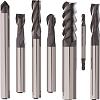
The How And Why Of Tungsten Carbide Inserts, And A Factory Tour - carbide milling insert for tool
“There are companies that require face grooves with major diameters as small as 0.2 mm,” says Duane Drape, national sales manager for Horn USA Inc., in Franklin, TN. “This is mostly aluminium, but I have had customer requirements to get that small with steel at 50 + Rockwell.”
Keep up to date with the latest news, events, and technology for all things metal from our pair of monthly magazines written specifically for Canadian manufacturers!

“This is a double-sided insert that works well with slow cutting forces,” says Kaufmann. “The GUP insert geometry is advanced and versatile, with excellent metal removing rates.”
Managing chip generation in tight spaces has always been a challenge, because the smaller the hole the harder it is to get the chip out. One approach is to plum or port the tool to get coolant out. There are also advanced tools, like Kennametal’s AF-GUP insert geometry for grooving and turning, that are specially designed for these challenges.
Morrison said, “A through-coolant system that is constant and consistent can maintain the heat absorbed by the insert at a fairly stable range to avoid thermal shock. Always use a clean, quality coolant and consider its oil concentration percentage.”
Chip load is also an area for attention, said Ball. “Not maintaining a constant chip load is one of the biggest issues I see in HSM. Consider whether the part you are machining and the tool you are using actually allow you to get to the feed rates you are programming. A widely varying chip load, or one that is too low or too high, will quickly wear out the tools.”
“The grades Iscar uses for our inserts depend on how fast the machine spindle can spin,” says Iscar Tool’s Geisel. “10,000 rpm sounds high but remember you are working with very small parts, around .100 in. in diameter. So that 10,000 rpm with a .100 in. diameter works out to be about 260 sfm…we need to design and produce the insert out of carbide grades with coatings that can run at such speeds.”
Easily access valuable industry resources now with full access to the digital edition of Canadian Fabricating & Welding.
“If coolant is needed, there are several application-specific delivery options such as axial coolant lines and coolant channels that come out at the cutting edge.”
Jay Ball, product manager--solid carbide end mills NAFTA, at Seco Tools LLC, said that it is important to have dedicated roughing and finishing tools. “Tight tolerances have become the industrial standard, and it is not uncommon for a customer to demand cutting tools with a 5-micron radius and diameter tolerance. Smaller tolerances are the wave of the future. To expect one tool to hold up during a roughing operation and use the same tool to finish and hold the tight tolerance is a stretch.”
As with most processes, the application determines the best tooling to use, but some rules of thumb should be considered for any HSM job.
“As a tooling manufacturer, we are being pushed to produce tooling able to groove in smaller, and smaller diameters. Our PICCO line can produce grooves in diameters from as small as 2 mm (.08 in.) and we can go smaller by special request.”
But replaceable inserts, single edge, can still get to some small diameters. More cost effective than a solid carbide tool, they can also deliver better axial depth. That said, solid carbide tools are usually more expensive, toolholders aren’t, and there is a risk the holder might break after a dozen or so uses.
At Hurco, we believe that our machines are designed and constructed to provide our customers with superior accuracy and rigidity and serve them well for many years. Watch the video to learn more.
“In hard milling you want to use an air/oil mist or air blast,” said Ball. “Coolant can thermal shock the cutting edge and prematurely wear out the tool. However, there are some cases where a manufacturer has to use coolant because it causes less wear than cutting hard chips. It’s a balancing act.
“The challenge with grooving is that below 1.5 mm it is difficult to make a tool that is strong enough,” says John Stewart, VP of engineering at Bokum Tool in Madison Heights, MI. “The overall determining factor is: What does a groove look like in a hole that size? If it is proportionally very similar to a larger hole then it is theoretically possible to get very small, but it really comes down to the strength of the tool itself.”
Depending on the manufacturer a tool may be designed with 1-1/2x, 2x, or 3x flute length diameter. The longer flute length is not as rigid as a short flute length so those tools may not work at the high speeds. Tools with shorter flute length need to be considered.
“If you are cutting to small major diameters on the face, where the grooves generally aren’t that deep, the chips are not an issue,” says Drape. “But in ID grooving applications where the groove is deep into a bore, then we need to get coolant in, and also need to break down the chip so it can evacuate.”
OSG’s A-BRAND® ADO-TRS drill is an advanced performance high-feed 3-flute carbide drill. Patented geometry provides stable chip ejection, even with less flute space inherent in 3-flute drills. The result is up to 3X faster cycle times and 3X longer tool life than 2-flute drills.
Luke Pollock, product manager at Walter USA, described a high-speed mill tool: “A common HSM mill tool uses a triangle-shaped insert with rounded edges. It is positioned in the cutter with a high lead angle, which allows the tool to take advantage of the chip thinning principle. As the tool is advanced, you get a chip thickness that is smaller than the advancement of the tool. For example, a 0.003-in. chip thickness is produced rather than the 0.005 in. that tool was advanced. These two values would be equal for a tool with a 90-degree shoulder.
“It is important to keep speeds as low as possible when you have small-sized parts,” says Igor Kaufmann, a member of Kennametal Inc.’s global team for turning tools. When grooving miniature parts, Kaufmann emphasizes that the tools still need to fit axially and apply radial force to the bore. As a result, it is hard to ensure that the tool is strong enough, which then leads not only to chatter issues but also challenges with breakage and chip evacuation.
Another approach is to compress chip width, thus ensuring it doesn’t lodge in the groove and result in tool failure. Either way, when it comes to grooving small parts, the combination of slow feed rates, proper tool selection, and a strategy for chip evacuation is the best way to ensure success.
The problem with carbide is that reducing deflection increases the risk a tool will break, so it’s important to preserve the strength of the neck of the tool. Tool monitoring is also recommended, because with small cutting edges it can be hard to see or hear when a tool breaks.
“The appropriate coatings will depend on the material being cut and the geometry of the insert,” said Pollock. “The geometry of the insert may require that the coating be very thin. And the thinner coating is typically better at heat resistance. A thicker coating will undergo more thermal expansion and doesn’t behave as well when heated—it can’t expand and contract as completely as a thin coat.”
High-speed machining (HSM) shaves time off metal removal processes. Low speeds and feeds that remove a large amount of material are replaced with light depths of cuts made at high feed rates. Metal is removed quickly, and the resulting near-net-shape parts, with surface finishes often from 10 to 12 RMS, reduce the semi-finish and finish operations.
Sue Roberts, associate editor, contributes to both Canadian Metalworking and Canadian Fabricating & Welding. A metalworking industry veteran, she has contributed to marketing communications efforts and written B2B articles for the metal forming and fabricating, agriculture, food, financial, and regional tourism industries.
Easily access valuable industry resources now with full access to the digital edition of Canadian Fabricating & Welding.
If the chip created by the grooving tooth is wider than the finished groove, then you can minimize the possibility that the chip will stay in the groove. But when it comes to harder metals the challenge isn’t chip control so much as creating the chip in the first place. “At 1.5 mm you need to have a tool that is strong enough to create the chip,” says Stewart. “But from there, with a strong alloy like Inconel, it is relatively easy to control the chip. In the case of aluminium and softer materials, where the chip is continuous, it creates greater headaches because the material balls up.”
Some tools combine roughing and finishing, but different cutting edges for each step help the tool to perform to close tolerances.
HSM generates a lot of chips very quickly. Ensuring their removal is critical whether you are dry machining and using an air blast, an air/oil mist, or using coolant.
“Exotic materials are not for production jobs—these are low volume applications,” says Tom Ficker, regional sales manager for Cogsdill Tool Products, Inc., with responsibility for Canada. “The problem with precision grooving in high nickel alloys is that you beat down on the grooving insert almost from the get-go.”
Solid carbide grooving tools are usually L-shaped. Part of the challenge is that even the non-cutting, or “leg” part has to fit into the bore diameter. Given that the bottom of the L, or the “foot” has to be even smaller, strength becomes an issue, as does the fact that groove depth is limited. As a result, with bores of less than 2 mm in diameter the best tools are now constrained to a groove depth of around 0.2 mm.
“The cutting process produces pressure on the work piece and on the tool. Controlling the pressure during machining dictates how successful we will be [in producing an effective cutting tool]. We can control cutting pressures by controlling the width of the grooving insert; the wider the insert, the more pressure it will produce. We also grind positive rakes on the inserts to control the pressure and to act as a chip former to control the chip shape and size.”
Geisel concurs with John Stewart that the challenge for tooling suppliers is to make a strong, rigid cutting tool or insert.
Tool balance is important when running at high RPMs. Most common tool designs with tool holders will work without a noticeable problem at speeds less than 7,000 to 8,000 RPM. But, over that speed, Morrison said you can start to see runout problems and decreased tool life.
As a result, Cogsdill’s tools are better suited to high production lines, an area that has seen some big changes of late. Only a few years ago, small bores were typically 4 mm, but now leading vendors are delivering off-the-shelf bore grooves to 2 mm, with specialty applications going much smaller. This has resulted in new abilities—and challenges—when it comes to grooving very small parts, as well as increased demand.
How best to approach grooving a small part has a lot to do with the materials involved: repeat, high volume applications tend to be with softer metals, with specialty one-offs applying to higher value applications, often with tougher alloys.
Ball said, “When you are high-speed machining you are taking a light radial and axial depth of cut, so you don’t have a tremendous amount of cutting pressure but you have to make sure your holds are rigid and balanced. You don’t see a lot of one-flute tools used in HSM because they are physically unbalanced by nature.
A frequent issue is whether or not to go with inserts or solid carbide tools. Inserts can be indexable or have only one edge for single use. Inserts tend to be less expensive, but usually can’t get into the smallest bores, and are not as strong as solid-carbide tools.
When grooving small pieces, cutting pressure tends to be relatively high. Aside from slowing feed rates, it can also help to use high lubricity coolants that work well in tight spaces.
“Shoot for stability, and use a tool for the process it was designed for,” said Cullen Morrison, business development manager, threading and milling, at KOMET of America. “One thing to consider is optimizing the tool design. Inserts with a large nose radius are better suited for high feed rates and heavy stock removal but are prone to chatter in small depth of cut, light feed rate finishing applications. If you are taking a large depth of cut with a small nose radius, it is likely to change the way the forces act on the insert and you may get chatter.”
“At higher speeds tool balance is exponentially more important as inertia begins to affect the tool, causing a compound problem of runout and imbalance that can even damage the machine spindle,” Morrison said. “Toolholder design also needs to be considered. Not all clamping systems will maintain their gripping force at a high rotational speed.”
“The geometries are not standardized, but there are ways to create space at the head of the tool to promote chip flow,” says Stewart. “Sometimes the actual grooving tooth on the cutting tool will have a chip breaker on it—this will help the chip move out and get flushed with coolant.”
Hydraulics, given their need to control pressure, create demand for inside diameter (ID) and outside diameter (OD) grooving seals and threads, as well as relief grooves. In the automotive sector, miniature grooving applications include fittings for air bags and fuel injection components.
Pollock said, “Sometimes air is adequate, but if it isn’t we prefer to use coolant just for getting the chips out of the way.”
High tool loads, especially in milling, bring out a system’s weakness. That weakness could be a poor rigid setup, a weak machine tool, or a loose bolt in fixturing that causes vibration. Machine tools are pushed to their limits for HSM, so the fixtures and tools have to be absolutely rigid to withstand the loads.
Tools for high-speed machining need to be rigid and as short as possible to avoid chatter or deflection. Photo courtesy of Walter USA.
Successful high-speed milling requires a balance among every aspect of the cutting system, including the machine tool, software, chip removal, and cutting tool. Photo courtesy of Seco.
Keep up to date with the latest news, events, and technology for all things metal from our pair of monthly magazines written specifically for Canadian manufacturers!
“You need the chips to be able to freely get out of the bore and away from the cutting action so they do not interfere with the machining process.”
“It would be preferable to take an indexable insert into small grooves, because it would be more economical. But you often have to go with a one piece design, using a brace tool with a carbide or carbon steel cutter brazed to it.”
“Slow feeds can be a good idea, depending on the material,” says Bokum Tool’s Stewart. “With smaller sizes a weaker tool neck will want to deflect, especially with carbide, and with increased distance to the groove, feed speeds need to be adjusted downward.”
“Tool manufacturers are adding tapered necks to some of the carbide tools, especially for the mould and die industry, so you have a stronger tool for a longer reach and the shanks of the tool will not rub the side walls of the mould cavity,” said Ball. “Those tapers increase strength by 10 to 20 per cent and give you the clearance to use a shorter, stubbier tool.”
Successful use of HSM depends on how the machine is programmed, how the tooling is used, and the tooling itself. Tools need to be designed for the higher speeds.
“Holders are critical for maintaining long, consistent tool life. It’s common for shrink fit holders to be used to hold the tight tolerances, but I also see the industry moving toward high-precision milling and collet chucks, as well as hydraulic chucks.”
“Another method would be to engage a small percentage of the tool diameter so you get the chip thinning effect that allows you to elevate speed rates. The roughing inserts--and HSM is basically a roughing process--have to have a stronger edge and tougher coating than the finishing inserts.”
The heat zone of a coating needs to be matched to what the tool is doing. Too much or not enough heat generation can cause a problem. Morrison said, “If the coating has a very low coefficient of friction, operations such as tapping may not generate enough heat to get the chip to break efficiently. The low heat level can create the tinfoil effect where the chip cannot break. Eventually chips build up in the hole and break the tap. If the coating cannot handle the heat generated by the operation, such as a high-feed mill, then it will break down quickly and expose the tool substrate, which will yield poor tool life.”
As with all applications, tool material and length-to-diameter ratio also affects HSM success. Morrison said that steel body tools are good to 3x or 4x diameter depending on the load. Carbide tools are better for HSM applications requiring a longer reach. Dampened steel tools can cut even further because they absorb vibrations happening at the cutting end.
ID grooving in particular can be an issue with small parts, says Steve Geisel, senior product manager for Iscar Tools Inc., Oakville, ON.


 18581906093