
Threading inserts - why different sizes? - threading insert types
90° cutting edge | D.O.C. max. 0.63" (16.0mm) • Positive axial rake, negative radial rake • 3D helical cutting edge for lower cutting forces • Wiper geometry for high-quality surface finishes • Superior perpendicularity and minimized cutting loads
90° cutting edge | D.O.C. max. 0.217" (5.5mm) • Superior perpendicularity and minimized cutting loads • Optimized for high-quality surface finishes • High rake angle lowers cutting loads and minimizes burrs • High-speed and high-feed capability imrpove productivity
In today’s lesson we looked at the first part of the ISO insert nomenclature for mechanically fixed inserts. To be precise we looked at the first 4 letters.
Material Type: Filter by primary workpiece material to find the inserts that are best suited for that specific material. You can also then filter by secondary workpiece material to find inserts that will cut multiple materials.
Round edge | D.O.C. max. 0.236" (6.0mm) • Superior perpendicularity and minimized cutting loads • Optimized for high-quality surface finishes • High rake angle lowers cutting loads and minimizes burrs • High-speed and high-feed capability improve productivity
90° cutting edge | D.O.C. max. 0.303" (7.7mm) • 90-degree shoulder mill • Double-sided, thick insert for high stability and deeper cuts • Inserts with 6 cutting edges
90° cutting edge | D.O.C. max. 0.394" (10.0mm) • Positive axial rake, positive radial rake • 35-degree rhombic inserts with two different nose radius options • High polish for excellent surface finish and reduced built-up edges • Large chipbreaker grooves for controlled chip evacuation • Low cutting forces due to the positive cutting edge

Depth of Cut: The maximum depth of cut (DOC) for a specific insert. The maximum DOC is affected by many variables, and may not be achievable under all conditions.
45° cutting edge | D.O.C. max. 0.236" (6.0mm) • Positive axial rake, positive radial rake • Large rake angle for faster, easier cutting • Inserts with 4 cutting edges
90° cutting edge | D.O.C. max. 0.571" (14.5mm) • Negative axial rake, positive radial rake • 90-degree shoulder mill with rectangle insert • Double-sided, thick inserts for high stability and deeper cuts
15° cutting edge | D.O.C. max. 0.071" (1.8mm) • 15-degree high feed mill • Inserts with 4 cutting edges • Ramping possible • Double clamping system for inserts
90° cutting edge | D.O.C. max. 0.217" (5.5mm) • Superior perpendicularity and minimized cutting loads • Optimized for high-quality surface finishes • 3-face clamping for stable operation in tough conditions • Suitable for plunge milling
But does this way of thinking fit well with our chip volume and productivity? Is this really the most economical way? Of course, we would say yes if we stopped at this level. But we like to go into each topic in depth, so let’s think about it.
First of all, let’s start by counting the number of cutting edges useful for our machining; the trigonal insert with its 6 cutting edges would be the master. The more cutting edges, the more pieces produced. Moreover, since the purchase cost of both inserts would be the same, the cost per cutting edge would be considerably in favour of the W-type insert; therefore, it will be cheaper per cutting edge. The W-type insert would definitely be the winner so far.
As we said in the lesson, the choice of shape influences the strength of the insert and its versatility in making profiles.
90° cutting edge | D.O.C. max. 0.591" (15.0mm) • Positive axial rake, positive radial rake • Sharp cutting edge geometry, and robust inserts • First choice for large cutting depths with high feedrates • Specially designed cutting edge, for high-quality shoulder milling
First of all, I would like to remind you that you can download the scheme of the ISO insert nomenclature. Keep it handy during today’s lesson and the next one, by clicking on the icon at the bottom right of the video. It will also come in handy on the machine. ISO insert nomenclature In today’s lesson we looked at the first part of the ISO insert nomenclature for mechanically fixed inserts. To be precise we looked at the first 4 letters. The first letter of the code is perhaps the most important one, that is the one that every turner must surely know because it defines the shape of the insert. In this lesson we have seen them all, although as we have said, in reality the most common shapes are as follows: As we said in the lesson, the choice of shape influences the strength of the insert and its versatility in making profiles. Among the various shapes, we find exactly in the centre the C and W shapes. Both have an angle between the cutting edges of 80° and both, for one reason or another, are among the most popular. C and W in comparison Let’s take a closer look at some practical aspects of the C and W shape inserts. Let’s compare them on the assumption that they have the same nose radius, the same solid carbide grade and identical chipbreaker geometry. C and W have different shapes – the first trigonal and the second rhomboidal – but both, once placed on the respective tool, tackle the machining with the same 95° tool cutting edge angle and therefore with a 5° lead angle. From the point of view of versatility, so the number of possible operations, both tools would be similar. Therefore they would be able to carry out the exact same machining operations for us operators: turning of various types, shouldering, chamfers and radius. So which one are we going to use? First of all, let’s start by counting the number of cutting edges useful for our machining; the trigonal insert with its 6 cutting edges would be the master. The more cutting edges, the more pieces produced. Moreover, since the purchase cost of both inserts would be the same, the cost per cutting edge would be considerably in favour of the W-type insert; therefore, it will be cheaper per cutting edge. The W-type insert would definitely be the winner so far. But does this way of thinking fit well with our chip volume and productivity? Is this really the most economical way? Of course, we would say yes if we stopped at this level. But we like to go into each topic in depth, so let’s think about it. Look at how the inserts are mounted on their respective tools; we should notice that the W-shaped insert would offer a slot with a more open contact angle due to its shape. The C-type insert, on the other hand, has a much better positioning from this point of view, since two of its sides are all positioned in the insert slot. This aspect becomes important when we have to start using the inserts in roughing operations when depth of cut and feed rates are high. The fact of having better stability in the case of the C insert is a fundamental advantage for cutting edge life and machining success. It is probable that the W-type insert will fail when heavily loaded due to the micro-vibrations created by the precarious fixing. Consequently, it is no longer so certain that we can use all 3 of its cutting edges, contrary to what happens with the C-shaped insert where we can certainly use both cutting edges. In our opinion, it should be used, for example, on machines where the working data are not so demanding. Its operations could be finishing and semi-finishing on materials that are not particularly difficult to machine. Because of its versatility and not only because of the number of operations it can perform but also because of the number of possible applications, from roughing to finishing, the C-type insert is undoubtedly the most widely sold and used insert in machine shops all over the world. It could be said that the C shape combined with its 95° lead angle has made the fortune not only of the insert manufacturers but also of us operators and workshop technicians, who have solved many problems with the use of this tool. In addition, the C shape placed on a different tool with a different lead angle would have a way of working with the so-called 100° recovery angle. In this way, the C-type insert would have 4 cutting edges instead of 2, making it one of the most affordable inserts. Used with recovery angles, it would certainly not be able to perform countless movements on the workpiece or remove large amounts of material. But within its field of application it would remain useful, also because the recovery angle assumes that the insert works at an angle between the cutting edges of 100°, so it is also very strong. This solution is successfully used in various sectors, for example when machining the surfaces of forged parts, roughing eccentric components where the interrupted cut affects the life of the insert. The first cut is often made in this way in order to improve and optimise production costs.
17.23° cutting edge | D.O.C. max. 0.07" (1.8mm) • Negative axial rake, negative radial rake • Positive rake angle for lower cutting forces • Strong vibration and impact resistance • Large chip pocket for smoother chip evacuation
This price includes shipping cost, export and import duties, insurance, and any other expenses incurred during shipping to a location in France agreed with you as a buyer. No other mandatory costs can be added to the delivery of a Haas CNC Product.
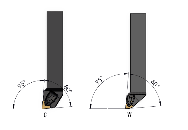
Among the various shapes, we find exactly in the centre the C and W shapes. Both have an angle between the cutting edges of 80° and both, for one reason or another, are among the most popular.
45° cutting edge | D.O.C. max. 0.138" (3.5mm) • Positive axial rake, positive radial rake • 45-degree cutting edge • Inserts have 8 cutting edges • Screw clamping
The first letter of the code is perhaps the most important one, that is the one that every turner must surely know because it defines the shape of the insert. In this lesson we have seen them all, although as we have said, in reality the most common shapes are as follows:
First of all, I would like to remind you that you can download the scheme of the ISO insert nomenclature. Keep it handy during today’s lesson and the next one, by clicking on the icon at the bottom right of the video. It will also come in handy on the machine.
90° cutting edge | D.O.C. max. 0.059/0.098" (1.5/2.5mm) • Double-sided inserts with 4 cutting edges • Unique geometry for lower cutting loads and longer life • High rake angle with strong, sharp cutting edges • Designed for high-efficiency plunge milling
It is probable that the W-type insert will fail when heavily loaded due to the micro-vibrations created by the precarious fixing. Consequently, it is no longer so certain that we can use all 3 of its cutting edges, contrary to what happens with the C-shaped insert where we can certainly use both cutting edges.
90° cutting edge | D.O.C. max. 0.67" (17.0mm) • Designed for high-speed machining of aluminum • Buffed surface for smooth chip evacuation and reduced BUE • High rake angle for good surface finish and lower cutting loads • For square shoulder milling and curved surface machining
In our opinion, it should be used, for example, on machines where the working data are not so demanding. Its operations could be finishing and semi-finishing on materials that are not particularly difficult to machine.
45° cutting edge | D.O.C. max. 0.217" (5.5mm) • Negative axial rake, positive radial rake • Double-sided inserts with 16 cutting edges • Special geometry for consistent cutting and long life • Strong insert and powerful clamping
Curved edge | D.O.C. max. 0.039" (1.0mm) • Low entering angle for high feedrates • High cost-efficiency, with 4-corner inserts • Positive rake angle for lower cutting forces • Wide flank face for rigidity and strong clamping
90° cutting edge | D.O.C. max. 0.649" (16.5mm) • Superior perpendicularity and minimized cutting loads • Optimized for high-quality surface finishes • High rake angle lowers cutting loads and minimizes burrs • High-speed and high-feed capability improve productivity
There are several variables that go into choosing the correct insert for your milling operations: the specific cutter body being used (milling cutter series), the type of machining operation (toolpath type), the cutting-edge angle (lead angle), the depth of cut, the materials being cut, and more. Use the filters on the left-hand side below to narrow down your choices, and find the inserts you need.
Because of its versatility and not only because of the number of operations it can perform but also because of the number of possible applications, from roughing to finishing, the C-type insert is undoubtedly the most widely sold and used insert in machine shops all over the world. It could be said that the C shape combined with its 95° lead angle has made the fortune not only of the insert manufacturers but also of us operators and workshop technicians, who have solved many problems with the use of this tool. In addition, the C shape placed on a different tool with a different lead angle would have a way of working with the so-called 100° recovery angle. In this way, the C-type insert would have 4 cutting edges instead of 2, making it one of the most affordable inserts.
Look at how the inserts are mounted on their respective tools; we should notice that the W-shaped insert would offer a slot with a more open contact angle due to its shape.
45° cutting edge | D.O.C. max. 0.275" (7.0mm) • Negative axial rake, positive radial rake • Double-sided, extra-thick insert with 8 cutting edges • Large rake angle reduces cutting forces • Wiper insert geometry for good surface quality

Milling Cutter Series: Filter by the Haas Milling Cutter Series to find all the inserts available for that specific cutter. If you don’t know the cutter series (or have a non-Haas cutter body), you can also filter by insert style (shape), or ANSI designation.
The C-type insert, on the other hand, has a much better positioning from this point of view, since two of its sides are all positioned in the insert slot. This aspect becomes important when we have to start using the inserts in roughing operations when depth of cut and feed rates are high. The fact of having better stability in the case of the C insert is a fundamental advantage for cutting edge life and machining success.
Used with recovery angles, it would certainly not be able to perform countless movements on the workpiece or remove large amounts of material. But within its field of application it would remain useful, also because the recovery angle assumes that the insert works at an angle between the cutting edges of 100°, so it is also very strong. This solution is successfully used in various sectors, for example when machining the surfaces of forged parts, roughing eccentric components where the interrupted cut affects the life of the insert. The first cut is often made in this way in order to improve and optimise production costs.
C and W have different shapes – the first trigonal and the second rhomboidal – but both, once placed on the respective tool, tackle the machining with the same 95° tool cutting edge angle and therefore with a 5° lead angle. From the point of view of versatility, so the number of possible operations, both tools would be similar. Therefore they would be able to carry out the exact same machining operations for us operators: turning of various types, shouldering, chamfers and radius.
Let’s take a closer look at some practical aspects of the C and W shape inserts. Let’s compare them on the assumption that they have the same nose radius, the same solid carbide grade and identical chipbreaker geometry.
45° cutting edge | D.O.C. max. 0.236" (6.0mm) • Negative axial rake, positive radial rake • Double-sided, extra-thick insert with 8 cutting edges • Low cutting loads and excellent smooth cutting


 18581906093