
TUNGSTEN CARBIDE INSERTS - tungston carbide insert
Another important factor to evaluate which is often underestimated is the corner radius of the cutting edge, for a correct application this should generally not be less than 2/3 of the "ap" cutting depth. In addition, factors such as surface finish, chip formation and cutting edge strength are linked to the insert radius.

The choice of the ideal insert for the turning processing is the first step towards optimising the production process, this passes through the evaluation of some primary and other secondary parameters that are also important.
Chip thickness is directly proportional to the angle of attachment, if the angle of attachment increases consequently the thickness increases but the width decreases, this cutting condition also affects the direction of the chip output.
For an optimal chip control, the insert’s field of application must be within the graphs in the catalogue, see example Tab 3.
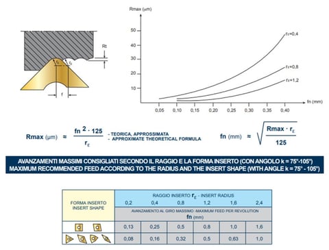
In Tab.5 there is an extract of the SAU catalog where the maximum feeds recommended are indicated according to the insert radius and theoretically approximate (but sufficiently reliable) the roughness that is obtained in relation between radius insert "rɛ" and feed "fn".
The type of machining also affects the size of the insert, this must be chosen according to the depth of "ap" pass and the type of insert used.
The choice of the ideal insert for the turning processing passes through the evaluation of some primary and other secondary parameters that are also important.
Generally the small radius has a weak cutting edge and is used for finishing operations with low cutting depth, where there are vibration problems and a better chip control. On the contrary, the large radius is a symbol of the sharpness of the cutting edge, great cutting depths and high feeds, this causes increased cutting forces and therefore risk of vibration.
Substrate or hard metal base, coating with PVD or CVD technologies and cutting edge geometry, create the ideal combinations for the processes required.
The figure in Tab.1 below identifies the ideal insert shape according to the profile that have to be executed, combined with Tab.2 which identifies the attachment angle or recording that affect the chip formation.
The trochoidal milling is a processing method that is used by using a radial engagement of the cutter combined with a higher cutting speed. Read more...


 18581906093