
TwoTrees 6.35mm Milling Bits for Woodworking - Set of 15 - machining bits
They’re not hard to set up. All you need is a kit, compressed air and a bit of oil. The whole package will cost you under $100 (assuming you have an air compressor), so if you use your router reasonably often it’s a really smart upgrade.
If you really have no choice and you have to plunge straight into the material, cut your feed rate waaaay down. Like if you’re running the profile cuts at 20 inches per minute, turn the plunge feed rate down to 4. Even then, pay close attention to see how it goes.
Cutting wax can be smeared all over the top surface of where you want to cut, and it’s great because it sticks on – even a downward exhaust won’t take it off.
This works amazing for work that will be done at a single or shallow Z depth, like when you’re working with sheet metal or engraving. If you’re doing deeper work with lots of Z levels, wax will do a better job of lubricating just the first pass.
HSS is cheap but not really all that great. That’s why you usually see a lot of HSS in high schools – when the students mess something up, it doesn’t cost the school as much (they’ll break the tools before they get a chance to wear), and nobody really cares how fast their cycle time is.
1) The machining handbook recommends a minimum RPM, so some people assume that the tool needs to be run at that RPM. That’s not what it means. It just means that you’re not achieving maximum efficiency for the tool. Not a big deal.
For the heavy duty CNC milling machines at work, my go-to was a 1″ diameter solid carbide roughing endmill for tough alloy steels.
Probably the simplest is just hanging out while it’s cutting and giving it intermittent sprays of WD-40. It you’re like me, you’ve probably already got 6 or 7 half-full cans of the stuff on your shelves and in your toolboxes. No reason to overcomplicate this.
For a 1/4″ tool on a rinky dink machine, try starting of at a depth of 0.010″ and go up in 0.010″ increments. For the same tool on a solid machine, try starting at 0.050″ and going up in increments of 0.025″. Listen for when the machine seems to be under load, or when the cut starts to look ugly.
A large nose angle is strong, but requires more machine power and has a higher tendency for vibration. A small nose angle is weaker and has a small cutting edge engagement, both of which can make it more sensitive to the effects of heat.
The insert shape should be selected relative to the entering angle accessibility required of the tool. The largest possible nose angle should be selected to provide insert strength and reliability. However, this has to be balanced against the variation of cuts that need to be performed.
This is why I really like using carbide 2 or 3-flute endmills whenever possible; they have enough chip clearance to reduce the chance of the aluminum welding itself to the cutter through friction, but they’re much stronger than the 1 flute endmills. Your cuts will look cleaner, and the tool won’t break as easily.
It’s really not a bad idea, though. If you want to do the upgrade and have the resources to pull it off, I’d definitely recommend installing one. I use mine all the time for plastics and metals.
Make It From Metal is owned and operated by Maverick Manufacturing Solutions. Make It From Metal is a participant in the Amazon Services LLC Associates Program, an affiliate advertising program designed to provide a means for sites to earn advertising fees by advertising and linking to Amazon.com. Make It From Metal also participates in affiliate programs with Bluehost, Clickbank, CJ, ShareASale, and other sites. Make It From Metal is compensated for referring traffic and business to these companies.
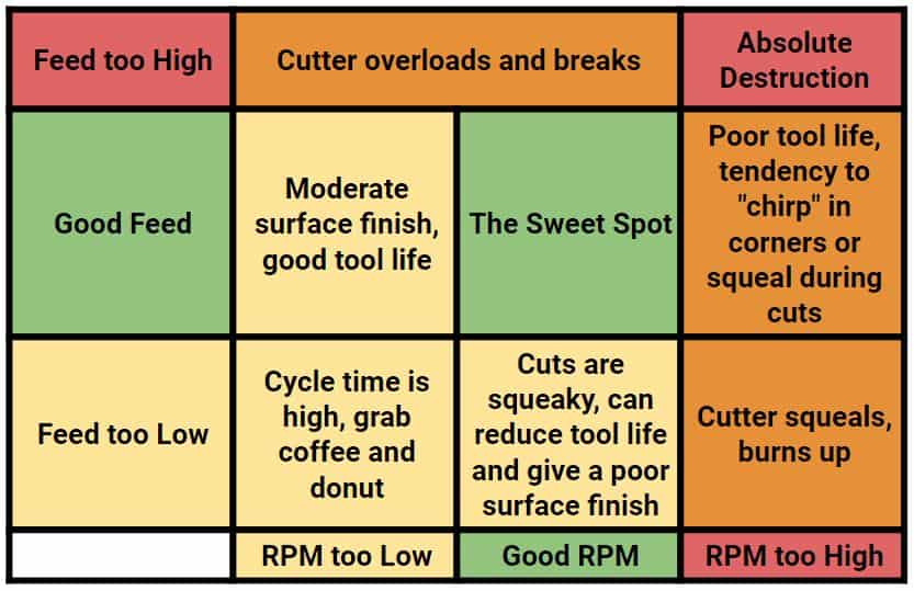
Honestly, you’re just going to need to play with it. That chart should give you an idea of what to look for to adjust the feeds and speeds to something that suits your machine.
This is because the tool is no longer under cutting pressure to stabilize it, and the vibration and runout cause the tool to make a slight gouge.
You’re going to want to use some kind of lubrication for aluminum. You can get by without anything for a short amount of time, but it’ll be riskier the longer you go without. If you’re planning on letting your router buzz away for 4 hours unattended, don’t expect your cutter to still be in one piece when you get back if it’s run dry.
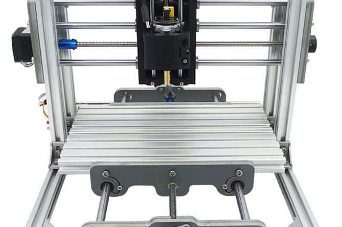
When I built my first router in my dad’s garage, I was really excited to make all kinds of things with plastic and aluminum. I went to school for machining, and I worked in shops with some pretty high-end CNCs.
Small tools work much better – but even still you need to know what kind of tool to use for aluminum. They’re different from plastic-cutting tools.
Don’t get too worked up about this. If your router is fixed RPM (or very limited) then just adjust based on feed rate and depth of cut. It ain’t rocket science, just make it work.
I really like using rebar for making all kinds of industrial-looking welding projects. It's also useful for things like reinforcing concrete, surprisingly. There are also a lot of different tools...
For a ramp on shape motion (some CAM software might call it something different) you’ll trace the profile that you’re wanting to cut while the tool slowly descends. It’s typically something like a zigzag motion. For most CAM software, it’s just a matter of checking a box and punching in your ramp angle. I usually go with something around two degrees.
When disengaging from the workpiece (like when the profile is cut and now it’s time to get the tool out of there) a straight retract usually works fine. The only problem that’s common is to have a notch on the part profile where the tool retracted.
Not so with routers. They’re way more finicky, and since each machine is a bit different, it’s almost impossible to know beforehand what the “sweet spot” is unless you know your machine well. A homemade hobby router will be very different from a large router that’s professionally built for aerospace composites.
Now it’s pretty unlikely that you have a 96,000 RPM machine, but this should give you an idea of how cutter diameter affects RPM. If your minimum speed is 30k RPM, then you might want to shy away from 1/4″ endmills for aluminum in favor of something 3/16″ or 1/8″.
If it’s heavy aluminum, try not to just jam the tool straight down. What works way better is a ramping motion to get down to the required Z depth for the cut.
Avoid plunging down into the metal whenever possible. Some tools are better designed for this that others, but it’s generally best avoided entirely. Unless you’re dealing with very thin sheet metal, that is. Then it’s not a big deal.
To counteract this, use an “arc-off” motion. Basically, instead of just having the tool stop on the part profile, add an extra little arc movement in the XY that will get the tool away from the finished geometry when it’s no longer under cutting pressure and free to leave a mark.
Select insert size depending on the application demands and the space for the cutting tool in the application. With a larger insert size, the stability is better. For heavy machining, the insert size is normally above IC 25 mm (1 inch). When finishing, the size can in many cases be reduced. How to choose insert size
Zhuzhou Sieeso Cemented Carbide Tools Co.,Ltd. Is a Chinese company that started operations in the year 2019, located in Zhuzhou City Hunan Province where is famous in the world for its tungsten carbide industry.
Basically, low spindle speeds are not a good reason to switch to HSS cutters. The only time that this makes sense is if you’re just starting out and you’re afraid of breaking a tool – Carbide is more expensive, but they work better and last significantly longer.
Forge welding is essentially the oldest way of joining two pieces of metal together. Some say that it's been around for almost 4,000 years, starting from when people were learning to smelt iron from...
Another factor is your RPM – larger tools need a lower RPM, so if you can get down to 15,000 RPM then the 1/4″ endmill will generally work well. If you can’t go less than 25,000 or 30,000 RPM then you might not want to use anything more than a 1/8″ or 3/16″ cutter.
I've been working in manufacturing and repair for the past 14 years. My specialty is machining. I've managed a machine shop with multiaxis CNC machines for aerospace and medical prototyping and contract manufacturing. I also have done a lot of welding/fabrication, along with special processes. Now I run a consulting company to help others solve manufacturing problems.
The textbook cutting speed for aluminum using a carbide tool is about 1,500 surface feet per minute at the high end, and 1,000 at the lower end. That’s not to say that you can’t spin it slower – you definitely can. But usually you don’t want to go faster than that.
2) Some cutters do need a minimum RPM to properly use their features. For example, you need to run some coated endmills at a minimum RPM to “activate” their coatings. You will not likely be entering this arena of high performance machining with a router.
This may or may not work. It’ll totally depend on how good your machine is. If your machine is home-made and reminiscent of a wet noodle, you might want to cut those feed rates down by half. If it’s a $100k machine, you could probably double it if you want to push it.
The -WMX wiper geometry is first choice, and is a good starting point for most applications. When conditions change, there is always a productive alternative. Choose a positive wiper geometry to lower forces and maintain productivity in case of vibration problems. Choose wiper geometry as follows: -WL:For improved chip control when moving to a lowerfn/ap. -WF:Improves chip control at a lowerfn/ap. Also for lower cutting forces when vibrations occur. -WMX:Always first choice within the wide chip application area. Provides maximum productivity, versatility and the best results. -WR:When a stronger edge line is needed, for example, for interrupted cuts.
There is an area where this doesn’t work the best: if you have a router with a downwards exhaust. I mean like those big Porter-Cable types of wood routers that have lots of power. They’ll blow a ton of air all around the tool, without actually getting air to the tool. It can be pretty tricky to get a decent spray around that air blast.
Over time, there will be dozens of tips and tricks that you’ll pick up. This should be enough information to get you started with some pretty cool projects.
If possible, get to your Z cut level off the workpiece, and then start cutting. That’s not always possible, though. Sometimes you need to get the tool in from the middle of a thick sheet.
The insert geometry and insert grade complement each other. For example, the toughness of a grade can compensate for lack of strength in an insert geometry.
Aluminum needs a lot more rigidity that wood or plastic. If you push it too fast, you might actually be able to see your machine flex under the load, if not rattle loose.
Not impossible, though. You can use those little red extension tubes that come with the can to help get the oil right to the tool. It’s just a little annoying because the air will blow away any oil that’s more than an inch or two away from the tool so you have to monitor it closely. I have a water-cooled spindle so it’s no problem for me, but it depends on your setup.

CNC mills and lathes are generally very predictable in how rigid they are. That’s why we can calculate optimal speeds and feeds without too much testing.
To get it to lubricate further down, you need to reapply it in that recently-cut channel. Not the end of the world, but I always like to let machines run without me babysitting them.
Use wiper inserts for improved surface finish with standard cutting data, or, maintained surface finish at substantially higher feed rate.
I've been involved in metalworking in its various forms for the past 14 years. On this website, I share some of the really cool things that I've learned while working in all kinds of different shops.
The entering angle, KAPR (or lead angle, PISR), is the angle between the cutting edge and the feed direction. It is important to choose the correct entering/lead angle for a successful turning operation. The entering/lead angle influences:
There are many parameters to consider when choosing turning insert. Carefully select insert geometry, insert grade, insert shape (nose angle), insert size, nose radius and entering (lead) angle, to achieve good chip control and machining performance.
The cutting parameters and quality of cut will depend a lot on how rigid your machine is. Small hobby routers and the big $100k machines are very different.
Turning geometries can be divided into three basic styles that are optimized for finishing, medium and roughing operations. The diagram shows the working area for each geometry, based on acceptable chip breaking, in relation to feed and depth of cut.
In general, you’d want to keep your chips small – something like 0.001″ per tooth for a 1/4″ endmill, and less than half that for a 1/8″ endmill.
Typically I’ll use a 1/4″ endmill since my machine can handle it well; I’ve done a few mods to make it a bit more rigid. If your machine is really little, you might want to use a 1/8″ endmill for cutting profiles.
Here’s a link to the 1/4″ endmill for aluminum. If you have a decently rigid home build, it should work fine. If you have a small machine, then you should start off by trying a 3/16″ or 1/8″ cutter. Those all have a 1/4″ shank so you don’t need to change your collet when swapping them.
For helical interpolation, you’re just making a spiral instead of a zigzag. This works well for holes, or when you’re making a pocket.
The nose radius, RE, is a key factor in turning operations. Inserts are available in several sizes of nose radius. The selection depends on depth of cut and feed, and influences the surface finish, chip breaking and insert strength.


 18581906093