
Which Carbide End Mill Hot Sale In Europe? - hot sales milling tool insert
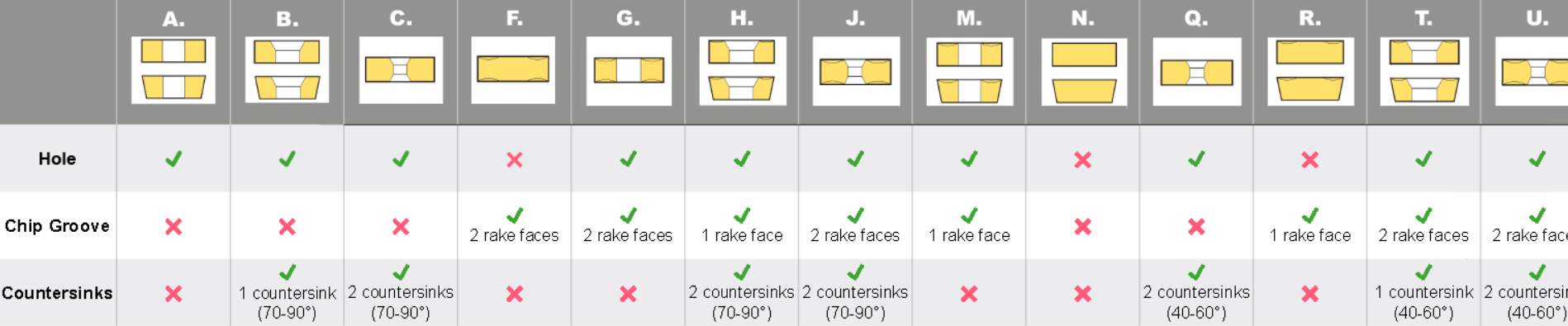
The cross-section highlights the differences in the design of the insert, such as the fixing holes, countersinks, and special features. This dictates what clamping method would be used to fix the insert on to the tool holder.
The chip breaker is represented as 2 letters in the ISO code. The chip breaker affects the cutting resistance, if the cutting resistance is low, it can avoid chipping and fracturing of the cutting edges. Reduced cutting resistance can also decrease the tool load and heat built up. The chip breaker also determines the depth of cut the insert can take, if you are not applying the correct depth of cut then you won’t be activating the chip breaker, this can cause the swarf to build up and become stringy, some people refer to this as a bird’s nest.
It is a 2-digit number that generally indicates the width or length, however this is only applicable to insert shapes with no IC (inscribed circle), such as rectangular and parallelograms.
It plays a crucial role in chip formation, tool life, cutting forces, and surface finish. Understanding the influence of the relief angle and selecting the appropriate one can greatly enhance machining performance, productivity, and the quality of the finished product.
In this blog, we will discuss how to identify all these key dimensions, so you will never need to check for part numbers again.
The nose radius of an insert can affect the performance. A larger nose radius can result in the use of higher feed rates, and larger depths of cut, and they can handle more pressure, making them much better for heavier metal removal. Whereas a turning insert with a smaller nose radius can only take smaller depths of cut, they also have weaker cutting edges, and they can only handle a small amount of vibration but are much better for finishing as they are sharper and have less surface contact.

Some of the below chipbreakers are available on both negative and positive inserts but the min-max depths of cut may vary.
Choosing the right insert shape for your turning tool is essential. The shape of the insert can affect the vibration during operation, the ability to turn complex contours, the strength of the insert and its ability to take bigger and heavier cuts.
All turning inserts have a unique ISO code that contains various letters and numbers – believe it or not, these actually mean something! From just looking at the ISO code you can figure out the insert’s shape, relief angle, tolerance, cross-section type, cutting-edge length, thickness, radius, and chip breaker!
For insert shapes such as round, square, triangle & trigon, this would then indicate the diameter of the inscribed circle (IC).
The thickness of a turning insert is measured from the bottom of the insert to the top of the cutting edge. This will be shown as a 2-digit number except where the insert features a T and then a single digit number eg T3. This is due to the fact that there are more than one increment within each mm. eg 03 is 3.18mm whereas T3 is thickest at 3.97mm.
Tolerance dimensions are indicated by a letter ranging from A - U. Dimension A relates to the inscribed circle (IC), dimension B relates to the insert height (for pentagon, triangle, and trigon shapes – for other polygons, the dimension B relates to the distance that is measured along the bisector of the corner angle) and dimension T relates to the thickness of the insert.
The relief angle for a milling insert is of paramount importance in achieving efficient and successful machining operations.

Each member brings with them their own experience and know-how to add to our growing pool of technical knowledge. That’s why our services are known for being the best in the business!


 18581906093