
Widin Carbide Rib Processing End Mill - 2 Flute Ball Nose ... - ball nose insert milling cutter
As the material integrity of ceramics has been improved, ceramics can be a viable alternative to carbide solutions, improving the life of the material to a similar duration as that of carbides.
When choosing carbide shapes, consider the highest possible nose angle to ensure the longest possible life of the insert.
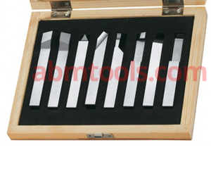
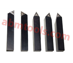
Top quality indexable lathe bits, with replaceable tips. Inserts can be rotated to a new cutting edge without changing the position of the tool holder (each has three sides). Turning tool set is ideal for a wide variety of projects. Supplied with right hand and left hand turning/facing tool holders,
The upcoming work will be easy for you once you have gained the knowledge of how to identify carbide inserts as a newbie. Carbide inserts are cutting tools that can be used to cut a wide variety of materials with high precision. Despite this, there are certain types of carbide inserts that can be used for cutting specific types of materials since not every insert can cut all types of materials. Thus, it is important for you to know what type of inserts are you using and when to use them.
The seventh position indicates a radius or a facet. Radius is given as 1 * 64 of an inch: 0 – sharp corner (0.002″ maximum radius); 0.2 – 0.004″; 0.5 – 0.008″; 1 – 1 * 64″; 2 – 1 * 32″; 3 – 3 * 64″; 4 – 1 * 16″; 5 – 5 * 64″; 6 – 3 * 32″; 7 – 7 * 64″; 8 – 1 * 8″; 10 – 1 * 16″
Typically, carbide particles are bonded together with a metallic binder in order to create carbides that are cemented together. The carbide particles act as aggregates and the metallic binder acts as the matrix. Sintering means the combination of the carbide particles with the binder, so it is a technology that combines the particles with the binder. The binder in this process gradually enters the liquid phase, while the carbide grains (which have a much higher melting point) remain in the solid phase. In reality, the binder is cementing the carbide grains, creating a metal matrix composite with the distinct material properties that it requires. Taking advantage of the naturally ductile property of metal binders, to offset the characteristic brittle nature of carbide ceramics, is one of the best ways to increase their toughness and durability. The carbide parameters can be modified significantly in this manner within the sphere of influence of the carbide manufacturer, mainly depending on the grain size, the cobalt content, the dotation, and the carbon content.
Based on the type of holder used, these inserts can cut grooves on both the outsides as well as the insides of a workpiece.
In addition to its high cost per unit, carbide is also very brittle, making it more susceptible to breaking and chipping when compared to other typical tool materials. Due to these factors, carbide cutting tips are often provided as small inserts within larger cutting tools that have steel hilts. The shank of the hilt is usually made of carbon, which is a more suitable material for the shank of the carbide cutting tip. As such, the carbide surface at the cutting interface is able to provide the benefits of using carbide without incurring the high costs and brittleness of making the whole tool from carbide. As with many of the modern lathe tools and endmills, most face mills these days have carbide inserts as well in them.
There is no doubt that tungsten carbide inserts can withstand pressure when it comes to performance under pressure. In order to produce this durable, extremely strong metal, grains of tungsten carbide are cemented into nickel or cobalt to create cement. Tungsten carbide produces a material second only to diamond in terms of hardness.
According to ANSI B212.4-2002, there was an additional capital letter O, which denoted other relief angles for design changes to indexable inserts.
In determining the tool holder to enter the tool, the depth of cut, and the machine specifications, consider the cutting length.
Coatings are sometimes used in order to increase the lifetime of carbide inserts. Generally, coatings designed to increase a tool’s hardness or lubricity will also increase the tool’s lubricity. By coating a cutting tool, it will be possible for the cutting edge to pass cleanly through things without the material galling or sticking to it. Besides lowering the temperature associated with the cutting process, the coating will also increase the tool’s longevity by preventing the tools from getting stripped out. As a rule, the coating is deposited using either thermal CVD or mechanical PVD methods, both of which are usually done at lower temperatures, depending on the application.
It is ultimately determined by such factors whether or not you will achieve satisfactory chip control and machining results.
There must be a simple system devised to categorise carbide inserts for their use since the sheer variety of carbide inserts on the market and their precision use require it. A series of letters and numbers are engraved on the centre of all steel cutting inserts, including carbide turning inserts. It refers to the ISO code system for turning tools that provides a simple method of identifying carbide inserts that can be used for narrowing the search for inserts. We discuss in this article a system of codes used to identify carbide inserts, and how I advise you to use the code system to identify your inserts.
With the combination of excellent heat resistance, better vibration and speed resistance, and the capability of cutting hard metals such as cast iron, ceramics are truly remarkable. Furthermore, this increase in the strength of the ceramic material also helps to prevent cracks from forming as a result of cutting the material.
The ceramic compound is added with small crystals of silicon carbide when whiskered ceramics are formed. There is a physical similarity between these crystals and whiskers, which is why this ceramic is called whiskered ceramic. With this kind of whisker, you can expect a machine to be a lot more resilient to vibrations and shocks.
When the grade is tough enough, the lack of strength in insert geometry can be compensated in part by the grade despite the lack of strength in the insert geometry.
The carbide insert thread mill is the term used to describe a piece of cutting insert that is used to create an internal or external thread within a part. These are typically attached to a tool holder on a lathe or a turning centre, where they are normally used with tools.
In particular, ceramic inserts are much superior to carbide inserts when it comes to heat resistance. The ceramic insert category encompasses several variations, but, generally speaking, all of the options fall under the category of providing solutions for the machining of extremely hard metals. Since ceramic inserts are heat-resistant, they can be used for lower production times as they are capable of cutting continuously at higher speeds due to their heat resistance. Due to reduced production times and lower costs, ceramic inserts are a good choice.
The indexability of inserts is controlled by 14 tolerance classes. Capital letters indicate each class. Tolerances are indicated by the letters A, B, C, D, E, F, G, H, J, K, L, M, U, and N.
A carbide insert is a cutting tool is tool that is used for machining different metals, such as cast iron, steel, carbon, non-ferrous metals, and alloys with a high melting point. The inserts of a carbide cutter are indexable, which means they can be swapped, rotated, or flipped without affecting the geometry of the cutting tool.
Letter A, B, and T indicate the tolerances on the dimensions (* from nominal). Insert dimensions are given by Dimension A. Inscribed circle diameter is given by Dimension A. Dimension T is the thickness of the insert. As a result, dimensions A and B are the corresponding dimensions for pentagonal, triangle, and triangular shapes.
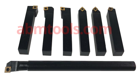
• Versatile of Cutting in any direction. • Built in Chip Breaker Groove. • Ready to Use. No Grinding. No Tool Resetting. • Heat treated and hardened shank • Economical alternative to Brazed Tool Tip. • Turning Tool Holder with indexable insert of Carbide Metal quality. • Have four cutting edges insert shape CCMT. • Set of 7 Pcs with Key. • Supplied with and without inserts.
The tungsten carbide used in cemented carbide is melted at an extraordinarily high temperature inside moulds. For saw blade tips, the moulds have pockets. These cemented carbide tips are then removed from the mould, placed on the saw blade tips, and brazed into place. A very sharp cutting edge is then created by grinding the tips. Except for the coating used on the tips, ceramic blades are formed the same way as carbide blades. There are also ceramic blades without teeth and with completely smooth edges. Blades with ceramic coating have very small diamonds embedded in the edge or tip. Diamond blades are commonly referred to as such because of this feature.
Carbide blades can be used to cut through wood, plastic, and metal, as well as a variety of other materials. Choosing the right blade for your material allows you to get smooth cuts using hard carbide tips. In terms of blades, the number of teeth, their shape, and if they are rounded or pointed, make a difference. It can be sharpened and reused for a long time when used correctly. On the contrary, the typical application of Ceramic Blades is to cut ceramic tile, porcelain marble, concrete, and masonry. They have a diamond coating that provides very clean and smooth cut results. Wet or dry applications are possible with this type of ceramic blade.
It is intended to identify the eighths of an inch in the nominal size of the I.C. It will have one digit whenever the number of eighths of an inch in the I.C. is a whole number: 1 – 1 * 8″; 2 – 1 * 4″; 3 – 3 * 8″; 4 – 1 * 2″; 5 – 5 * 8″; 6 – 3 * 4″; 7 – 7 ⁄ 8″;
Carbide inserts are available in a wide range of types depending upon your application requirements. Below is a list of some of the major types of carbide inserts you are likely to encounter in your everyday life.
The selection of carbide shapes should be based upon ensuring that it is a relatively essential tool for entering angles into the tooling process.
A number of parameters must be taken into consideration when choosing the right carbide inserts. It is possible to find China carbide inserts manufacturers who provide quality material, but why take the chance? It is possible to find China carbide inserts manufacturers who provide quality material, but why take the chance?
With its high accuracy and high-performance indexable inserts, the Drilling and Hole Boring System is suitable for use on materials as diverse as aluminium and superalloys. With the drill body made of heat-treated steel that is very rigid, the nest for the insert is rigid and the flutes are straight, resulting in a long term life for the insert and an efficient chip removal process.
A standard called ANSI B212.12-1991 describes nine different relief angle values. The angle between the flanks of an insert and the top surface of the insert is calculated by measuring the distance from 90° in a plane normal to the cutting edge. Typical relief angles are denoted as follows:
You can take advantage of inserts carbide in numerous possible ways. You can use carbide lathe inserts for machining various materials.
In addition to thread mills and thread rolling, the use of thread inserts is another method for creating threads on a workpiece similar to thread milling. It is important to put these replaceable commodities in their proper places as replacements wear out.
Fourteen standard types of insert are referred to using capital letters, and these variations include fixing holes, countersinks, and special features on rake surfaces.
Inserts made of cemented carbide are available in several sizes, shapes, and compositions that are used in various manufacturing methods on steels, cast iron, highly ferrous alloys, and nonferrous metals. In addition, machining metal parts more efficiently and with better finishes can be done when using carbide inserts. In addition to steel, stainless steel, hardened steel, cast iron, non-ferrous metals, titanium, and boring inserts are also good choices for applications.
A turning tool body grips a replaceable insert which is attached to a lathe turret. Turning is typically done with a replaceable insert. Inserts for turning tools are manufactured using composite materials, coatings, and geometry features that provide high accuracy and high material removal rates.
In the sixth position, there is a significant one- or two-digit number representing the thickness of the insert in sixteenths of an inch. Whenever the thickness of a piece is a whole number: 1 – 1 * 16″; 2 – 1 * 8″; 3 – 3 * 16″; 4 – 1 * 4″; 5 – 5 * 16″; 6 – 3 * 8″; 7 – 7 * 16″; 8 – 1 * 2″; 9 – 9 * 16″; 10 – 5 ⁄ 8″.
Five digits indicate the diameter of the inscribed circle (I.C.) for all inserts that have a true I.C. such as Rounds, Squares, Triangles, Trigons, Pentagons, Hexagons, Octagons, and Diamonds.
Among the multitude of applications for which groove-making tools are relevant, there is a vast variety of hardware components of all types. These Carbide specialists specialize in determining the precise specifications required to perfectly suit the needs of each customer, regardless of whether they are parting off a smaller component or creating a deep groove with a large diameter. A Carbide insert can be grooved efficiently and expertly for extrusion grooving, internal grooving, face grooving, as well as parting. To maximize productivity and efficiency, you need to make sure that you choose the right tool. Every groove comes with its own set of challenges, no matter how wide or shallow it is. Additionally, every material used in the manufacturing of the component has its own set of properties and limitations. It is these three elements that truly determine how the ideal tool should be designed, sized, and rated for the job.
In order to protect and maintain the integrity of ceramic materials, precautions must be taken in the use of machines to keep excessive vibrations to a minimum. Ceramics are naturally more brittle than carbide alternatives. The ceramic compound is augmented with additional components that prevent this brittle tendency and increase its longevity.
When the seventh position contains letters, the 10th position will only be used. The number represents a nominal measurement of sixty-fourths of an inch in length: 1 – 1 * 64″; 2 – 1 * 32″; 3 – 3 * 64″; 4 – 1 * 16″; 5 – 5 * 64″; 6 – 3 * 32″; 7 – 7 * 64″; 8 – 1 * 8″; 9 – 9 * 64″; 10 – 5 ⁄ 32″.
Unless otherwise specified, dimensions A and B refer to the distance measured along the bisector of the rounded corner angle and a gage roll of nominal I.C. For instance, if tolerance letter H shows 0.005″ on A, 0.0005″ on B, and 0.001″ on T, so dimensions (* from nominal) are: A, B, and T.
Additionally, these tools can be removed from the tool body, which means that the tools are not welded or brazed together. This type of tool can be used at high speed, which means you can create better surface finishes on your materials as a result of faster machining.
An ideal nose angle would be a big one but it would be more complicated and require a lot more resources. Furthermore, it would be more likely to cause vibrations. As a result, a small nose angle will have a low cutting edge engagement and may not perform as well as a large angle. It is, therefore, more prone to the diverse effects of heat and has a heightened sensitivity to them.
Set Consist of following (7 Pcs Set) Left Hand Turning Tool – for Straight turning – 1 Piece Right Hand Turning Tool – for Straight turning – 1 Piece Right Hand Facing Tool – for Face turning – 1 Piece Right Hand Straight Turning Tool – for Straight turning – 1 Piece Pointed Turning Tool – for outside thread turning and straight turning – 1 Piece Off Pointed Turning Tool – for outside thread turning and straight turning – 1 Piece Boring Bar for right hand cutting – for turning out internal bores – 1 Piece
The term milling insert refers to a piece of equipment that can be used to process materials such as steel and titanium without the fear of breaking the tool. The materials they help shape, they can straighten, shape, cut, and they can also cut metals such as steel, stainless steel, cast iron, non-ferrous materials, titanium, hardened steel, and plastic.
Make sure that you choose your carbide insert size according to the particular machining requirements and the availability of cutting tools in your position.
If you are planning on using a carbide insert when you are cutting particulates or foam, you will have to make sure you choose the right insert. A preventative method can reduce the number of damage cases to the insert, as well as the machines as well as the workplace in general. Among the different styles, sizes and grades of cutting tools available in the market today.
A capital letter indicates 10 positions in the indexable insert as per the ANSI B212.4-2002 standard. There are ten positions (1-10), which define the characteristics of an insert as follows:
Corporate Address :ABM TOOLS, 79-A, Block GG-1, Vikas Puri,New Delhi – 110018, IndiaFactory Address :Plot No 132/6, Block RZ-Q, Nihal Vihar, Gurudwara Road,Near 500 Sq. Yard Gurudwara, Opp Bharat Properties , Nangloi, Delhi – 110041, IndiaMobile / whatsapp : +91 98910 27608 +91 98712 63436 +91 98910 44387
In the ninth position is a capital letter that indicates the hand of an insert: R – Right Hand; L – Left Hand; N – Neutral.
The width and length dimensions of rectangular and parallelogram inserts are used instead of the I.C. The size of these inserts is indicated by a two-digit number. A first digit indicates how many eighths of an inch the insert is wide and a second digit shows how many fourths it is long.


 18581906093