
Grooving the small stuff - carbide insert groover
In general, Howard believes there’s a fairly widespread lack of knowledge about ceramic cutting tools in the machining industry. So he had no trouble identifying some lesser-known applications for these tools. One is cutting hardened stainless steel.
Another invention of late that may interest shops that haven’t tried ceramic tools in a long time is a patented material called Bidemics. Howard describes Bidemics as an advanced ceramic designed to conduct more heat away from the cutting edge.
As for Greenleaf’s solid-ceramic endmills, Dillaman said they can speed up machining of hardened materials normally done entirely with EDM operations.
The μ-LAM technology directly heats and thermally softens the workpiece material, in the chip deformation and generation zone, increasing the material's ductility. Improved ductility that results from reduced material hardness allows for easier chip formation, decreased brittleness, and ultimately higher material removal rates-all leading to better tool performance and increased productivity that in turn translates into lower manufacturing costs.
“Stainless steel is an area that a lot of people never think of ceramic for,” he said. “It’s got to be hard, though — above, say, 32 to 35 Rockwell — because we’re going so fast and (therefore) cut so hot.” If the steel is below that hardness level, “you will melt it and light it on fire.”
In addition to Si, the μ-LAM process also improves productivity for other crystals and IR materials (see Table 2). μ-LAM is also an enabling technology, producing high-quality, large-diameter Si optics and all sizes of CaF2 optics compared to zero acceptable parts using conventional diamond turning alone.
Because they do a better job of transferring heat away from the cutting edge, Bidemics inserts can run even faster than typical ceramic cutters — close to 1,600 sfm, Howard said. He added that efficient heat transfer also lengthens the life of cutting edges.
William Leventon is a contributing editor to Cutting Tool Engineering magazine. Contact him by phone at 609-920-3335 or via email at wleventon@gmail.com.
When people tell Howard that they tried ceramic tools for a particular application and it didn’t work, he asks when they tried ceramics. Sometimes, it turns out that the failed ceramics experiment wasn’t even in this century. So he tells these people, “Well, we’ve invented a few things in the last 20-some years.”
When it comes to ceramic cutting tools, don’t believe the old saying, “What you don’t know can’t hurt you.” A lack of knowledge about ceramic cutters can put a big hurt on shop productivity. What’s more, even shops that are somewhat informed about ceramic cutting tools often aren’t getting the most out of the tools because they are unaware of lesser-known applications that are a good fit for ceramic machining, let alone recent developments that make the ceramic option more attractive than ever.
“So people say they’re going to go really, really slow and change tools a lot,” Howard said. “But when we get a few brave people that let us play with ceramic, they go, ‘Oh, my God, I never knew I could do this.’”
“If somebody is cutting heat-resistant alloy at 125 sfm, and you bring in this new product that can do 1,600 sfm, it’s kind of like taking somebody from a horse to a rocket ship,” he said. So sometimes “the (reaction) is, ‘There’s no way I’m doing that.’”
Wheel formed from abrasive material mixed in a suitable matrix. Takes a variety of shapes but falls into two basic categories: one that cuts on its periphery, as in reciprocating grinding, and one that cuts on its side or face, as in tool and cutter grinding.
“When they invented this stuff, tooling people loved it because it just carves up cutting tools,” he said. “And the cost justification wasn’t there to go to CBN or PCD because it wears that stuff out too.”
Although the increased hardness in Si is preferred to minimize part failure during service, it also makes it much more difficult to machine. The hardness and abrasiveness of Si causes the diamond tool to rapidly wear, yielding poor part quality and high form errors. The μ-LAM process has shown significant benefits in machining Si and other optical crystals, as it temporarily reduces the workpiece material's hardness, resulting in significantly less tool wear.
Dillaman said these endmills are made from the company’s Xsytin-1 material, which features a “whisker,” or reinforcing material, that’s grown internally via processing rather than laid in. This makes the ceramic material much harder to break apart, he said. He added that Xsytin-1 has shown itself to be capable of handling challenging roughing applications and turning interruptions.
“We found a way to fuse carbide and ceramic together without a cobalt binder,” Howard explained. “The carbide is introduced into the ceramic in kind of a spiderweb fashion. When heat hits the cutting edge, it runs down those little carbide trails and disperses more efficiently.”
Machining operation in which material is removed from the workpiece by a powered abrasive wheel, stone, belt, paste, sheet, compound, slurry, etc. Takes various forms: surface grinding (creates flat and/or squared surfaces); cylindrical grinding (for external cylindrical and tapered shapes, fillets, undercuts, etc.); centerless grinding; chamfering; thread and form grinding; tool and cutter grinding; offhand grinding; lapping and polishing (grinding with extremely fine grits to create ultrasmooth surfaces); honing; and disc grinding.
Substance used for grinding, honing, lapping, superfinishing and polishing. Examples include garnet, emery, corundum, silicon carbide, cubic boron nitride and diamond in various grit sizes.
To evaluate the machinability of optical-grade crystals via the μ-LAM process, machining tests were performed on a diamond-turning ultra-precision lathe (UPL) with a 15 pm positional accuracy feedback system. Such UPLs are designed for producing optical lenses, optical mold inserts and mirrors, and small precision mechanical components.
In addition, he noted that ceramic tools are more expensive than their carbide counterparts. When it comes to tools with inserts, he said this is because ceramic inserts require a good deal of grinding while carbide inserts are easily mass-produced.
Substances having metallic properties and being composed of two or more chemical elements of which at least one is a metal.
Process that vaporizes conductive materials by controlled application of pulsed electrical current that flows between a workpiece and electrode (tool) in a dielectric fluid. Permits machining shapes to tight accuracies without the internal stresses conventional machining often generates. Useful in diemaking.
The main advantage of ceramic tools is the effectiveness with which they handle the heat generated by the cutting process.
Even if shops aren’t put off by the higher cost of ceramic tools, shops may be unable to make proper use of the tools because their equipment can’t match the speeds for which ceramic tools have the capacity. Or shops actually may be afraid to reach those speeds.
“Some customers were using OD grinding or surface grinding for hardened materials just because that’s the traditional method that has been used,” Dillaman said. “But with ceramic inserts, you can remove large amounts of material much quicker than you could in a grinding application.”
For our analysis, the μ-LAM system was mounted on a UPL to machine a diffractive Si lens (see Fig. 1). The μ-LAM system's tool post, termed Optimus T+1, is a bolt-on system that replaces the existing tool post and takes <60 min to retrofit. The laser controls are connected to the UPL, enabling it to be controlled with an M-code command.
To demonstrate extended tool life, many Si diffractive lenses were machined using the μ-LAM process and analyzed for surface roughness and form error using a white light interferometer with a standard Gaussian 0.08 mm filter applied. Note that the part numbers correspond to the order in which they were machined—for example, part 12 would be the 12th part the tool would have machined.
Deepak Ravindra is CEO, Sai Kumar Kode is lead process engineer, and Chris Stroshine is global sales manager, all at Micro-LAM, Portage, MI; e-mail: [email protected]; www.micro-lam.com.
Machining of a flat, angled or contoured surface by passing a workpiece beneath a grinding wheel in a plane parallel to the grinding wheel spindle. See grinding.
A ceramic endmill removes material much more quickly than an electrode, he said, and use of an endmill should slash the number of electrodes needed for the overall process, as well as the time spent creating them.
Dimension that defines the exterior diameter of a cylindrical or round part. See ID, inner diameter.
Milling cutter held by its shank that cuts on its periphery and, if so configured, on its free end. Takes a variety of shapes (single- and double-end, roughing, ballnose and cup-end) and sizes (stub, medium, long and extra-long). Also comes with differing numbers of flutes.
Compared to standard diamond turning, the μ-LAM process not only produces good Si part quality with more than 3X reduction in surface roughness, but it also enables increased manufacturing productivity, more than quadrupling the number of parts that can be produced in a single shift (see Table 1).
A typical Si diffractive lens used in an IR optical system with a 50.4 mm diameter, for example, has a 0.5 fringe irregularity tolerance, surface roughness <10 nm Sa, 60-40 surface quality, no spokes, and no gray or brittle bands. The primary challenge here is achieving the 0.5 fringe (<160 nm) irregularity tolerance that can only be achieved with a well-preserved (not worn) cutting tool edge.
Information about these applications usually falls into the category of what people in the machining industry don’t know about ceramic cutting tools. Equally frustrating for the firms that sell these tools, however, is what many people think they know based on outdated information.
At Greenleaf, Dillaman and his colleagues have had success using ceramic inserts to replace grinding in some cases.
After optimizing such machining parameters as the depth of cut, cross feed, cutting speed, and laser power, several Si lenses were fabricated and evaluated for their surface finish (roughness), surface aesthetics (spokes, brittle bands), form accuracy or irregularity tolerance, tool life (based on the number of parts fabricated), and productivity (pushing the machining parameters to enhance production).
In recent years, Bidemics has become popular with makers of larger aerospace engines, Howard said. But he added that some shops find the performance boost offered by the material a bit unsettling.
A wide range of materials, including metals and alloys, ceramics, glasses, semiconductors, and composites, are manufactured to meet service requirements to a given geometry, accuracy, finish, and surface integrity. Metals and alloys in general are easier to machine because of their high fracture toughness, low hardness, non-directional bonding, low porosity, large strain to fracture, and high impact energy. On the other hand, non-metals such as ceramics, semiconductors, optical crystals, and many infrared (IR) optical materials are characterized by covalent or ionic bonding, limited slip systems for plastic deformation, high hardness, and low fracture toughness, making them more challenging to machine.
Workpiece is held in a chuck, mounted on a face plate or secured between centers and rotated while a cutting tool, normally a single-point tool, is fed into it along its periphery or across its end or face. Takes the form of straight turning (cutting along the periphery of the workpiece); taper turning (creating a taper); step turning (turning different-size diameters on the same work); chamfering (beveling an edge or shoulder); facing (cutting on an end); turning threads (usually external but can be internal); roughing (high-volume metal removal); and finishing (final light cuts). Performed on lathes, turning centers, chucking machines, automatic screw machines and similar machines.
Another lesser-known ceramic application cited by Howard is cutting powder metal, which is popular in the automotive industry.
A relatively new entry in the ceramic tool market from Greenleaf is its Xsytin-360 line of solid-ceramic endmills. Launched last year, Xsytin-360 endmills come in standard diameters down to 3/8", so they can cut much smaller features than indexable tooling.
Cutting tool materials based on aluminum oxide and silicon nitride. Ceramic tools can withstand higher cutting speeds than cemented carbide tools when machining hardened steels, cast irons and high-temperature alloys.
Hardness is a measure of the resistance of a material to surface indentation or abrasion. There is no absolute scale for hardness. In order to express hardness quantitatively, each type of test has its own scale, which defines hardness. Indentation hardness obtained through static methods is measured by Brinell, Rockwell, Vickers and Knoop tests. Hardness without indentation is measured by a dynamic method, known as the Scleroscope test.
“The big thing with ceramic is it conducts heat better than anything else,” said Steven Howard, marketing and engineering manager at NTK Cutting Tools USA in Wixom, Michigan.
Depending on the amount of material needed to make an insert, ceramic inserts could be anywhere from 1.5 to four times more expensive than inserts made of more commonly used materials, said Martin Dillaman, global manager of engineering and applications at Greenleaf Corp. in Saegertown, Pennsylvania. Dillaman added that solid-ceramic tools probably cost two to four times as much as their counterparts made of more widely used materials. He added, however, that the higher cost of ceramic tools can be justified by savings in cutting time and throughput increases at shops that use them.
“Traditionally, you have to use an electrode to burn material out of a hardened workpiece,” he said. “With our solid-ceramic endmills, (you can) use the endmill to remove the bulk of that material instead of having to create an electrode to remove the full amount of material.”
Howard also noted that ceramic tools are a good choice for cutting compacted graphite iron, which he described as a fairly new type of cast iron that’s very dense and strong. Today, he said, CGI is used to make many diesel engines because it allows manufacturers to use a smaller engine block that can take more compression.
With a less-than-eight-month payback, the μ-LAM system is proving its worth for many IR optical materials and crystals, with productivity improvements up to 500%, machine efficiency increases up to 200%, and improved part quality. μ-LAM processes are also being developed for ultrahard materials such as silicon carbide (SiC), sapphire, spinel, glass, and some selected metals used in the optics and aerospace industries.
Optical-grade Si is typically used as a lens for IR imaging systems. Previously, Ge was a favored material, as it is typically easier (softer) to machine. However, there are several advantages of Si over Ge, such as lighter weight, lower cost for the bulk material, and better thermal stability and mechanical properties-primarily higher hardness.
Cast iron having a graphite shape intermediate between the flake form typical of gray cast iron and the spherical form of fully spherulitic ductile cast iron. Also known as CG iron, CGI or vermicular iron, it is produced in a manner similar to that of ductile cast iron but using a technique that inhibits the formation of fully spherulitic graphite nodules.
1. Permanently damaging a metal by heating to cause either incipient melting or intergranular oxidation. 2. In grinding, getting the workpiece hot enough to cause discoloration or to change the microstructure by tempering or hardening.
Recently, μ-LAM technology has made some groundbreaking progress in machining optical-quality tungsten carbide (WC) using a diamond-turning process. While favored in the glass molding industry, as it performs well under high temperature and high-pressure applications, WC is an extremely hard material (about 3X harder than Si) and, therefore, has never been successfully diamond-turned to an optical quality surface. The status-quo process to manufacture WC optical molds is to grind and polish them in an arduous 3–4 hour per-part process.
He pointed out, however, that NTK makes ceramic tools that can cut CGI for 10 times less than the cost of carbide tools. But few in the industry know this.
Cutting tool material consisting of natural or synthetic diamond crystals bonded together under high pressure at elevated temperatures. PCD is available as a tip brazed to a carbide insert carrier. Used for machining nonferrous alloys and nonmetallic materials at high cutting speeds.
Dillaman also reported that Greenleaf got good results when it pitted ceramic inserts against PCD in an aluminum-cutting application for a customer. He said the ceramic inserts that were used showed little wear and held up as well as their PCD counterparts. The biggest downside for ceramic inserts was the accumulation of some built-up edge that had to be removed.
When cutting with common tool materials, such as carbide, CBN and PCD, heat is not conducted away from the cutting edge, which eventually breaks down as a result, Howard explained. By contrast, he said, ceramics do a good job of transferring heat away from the cutting edge, thereby extending its life and the life of the tool as a whole.
Crystal manufactured from boron nitride under high pressure and temperature. Used to cut hard-to-machine ferrous and nickel-base materials up to 70 HRC. Second hardest material after diamond. See superabrasive tools.
“You may still have to do some finish work with an electrode, but the amount of electrodes consumed should be much reduced,” he said.
A new technology called micro-laser-assisted machining (μ-LAM) is gaining traction for machining optical crystals and IR materials including silicon (Si), calcium fluoride (CaF2), zinc selenide (ZnSe), germanium (Ge), and zinc sulfide (ZnS). As evidenced by a materials study undertaken at Micro-LAM, the value proposition for μ-LAM technology includes extended tool life, increased productivity, and improved part quality during the manufacture of optical crystals and IR optics.
On the downside, Howard pointed out that the hardness of ceramic materials makes them brittle, so those who make tools out of ceramics can’t put very sharp edges on them. As a result, he said, ceramic tools don’t cut as efficiently as carbide tools.
The amount of heat produced during the cutting process is a function of the cutting speed and the material being machined. So the ability of ceramics to conduct heat away from the cutting edge means that ceramic tools can run much faster than those made of carbide, CBN or PCD when cutting most materials, Howard said. He noted that while carbide tools cut heat-resistant alloys at 125 sfm, for example, ceramic tools can cut them at anywhere from 800 to 1,500 sfm.
Ceramics “run so much faster” than carbide, Howard said. “And with that comes a lot of fear. People say, ‘Wow, I can’t control this thing because I don’t have enough knowledge or skill.’”
Tangential velocity on the surface of the tool or workpiece at the cutting interface. The formula for cutting speed (sfm) is tool diameter 5 0.26 5 spindle speed (rpm). The formula for feed per tooth (fpt) is table feed (ipm)/number of flutes/spindle speed (rpm). The formula for spindle speed (rpm) is cutting speed (sfm) 5 3.82/tool diameter. The formula for table feed (ipm) is feed per tooth (ftp) 5 number of tool flutes 5 spindle speed (rpm).
In addition, he noted that users of ceramic inserts in these cases aren’t limited by the form on a grinding wheel. Instead, they can program different cutting profiles to meet different requirements.
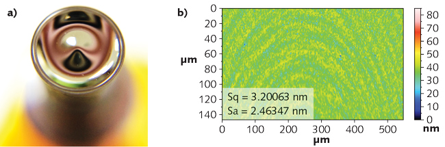
For a 17-mm-diameter WC part, machining time is 90 seconds. With a required Sa spec for this <5 nm part, the μ-LAM process yielded roughness values of 2 to 2.5 nm.
“That material is both abrasive and creates heat, and those are the things that wear out tools the fastest,” he said. So for this application, “people will go from carbide straight to CBN, and the cost difference between those two is astronomical.”
The Optimus T+1 was coupled to a 1064 nm yttrium aluminum garnet (YAG) laser via a fiber-optic cable and collimated lens. The diamond tool is optically transparent to the wavelength of the laser and fabricated to perform as a focusing lens that directs the beam precisely to the tool's cutting edge radius. This allows for only the cutting zone of the material to be heated and softened.


 18581906093