(HMQ) Quart/Cup Helix Mixers, 2-Pack - helix tools
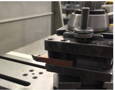
8. Grind a slight radius on the point of the cutting tool, being sure to maintain the same front and side clearance angle.
2023220 — Cobalt alloys have excellent strength and toughness, high-temperature strength and resistance, and good corrosion resistance.
7. Move the threading tool up to the part using both the compound and the cross feed. Set the micrometer to zero on both dials.
6. Nose radius: The radius to which the nose is ground. The size of the radius will affect the finish. For rough cut, a 1/16 inch nose radius used. For finish cut, a 1/16 to ⅛ inch nose radius is used.
CS CUTOUTIL is one of the most professional carbide inserts-cutoutil manufacturers and suppliers in China, specialized in providing high quality cutting ...
Manufacturing Processes 4-5 Copyright © by LamNgeun Virasak is licensed under a Creative Commons Attribution 4.0 International License, except where otherwise noted.
... Woodworking Tool 140x42mm Board File RC Replacement Spare Blade, for Shaping & Chamfering Wood ... Tool for Resin, Hand Deburring Tool ...
• Side Relief (clearance) angle: The angle ground on the flank of the tool below the cutting edge. This angle may be from 6 to 10 degrees. The side clearance on a tool bit permit the cutting tool to advance lengthwise into the rotating work and prevent the flank from rubbing against the workpiece.
Triangle shape cbn tool inserts with 16.5mm(0.65in)X4.76mm(3/16in).The grade TBN20 is suitable for moderately interrupted&continuous turning of hardened ...
• End Relief (clearance) angle: the angle ground below the nose of the tool bit which permits the cutting tool to be fed into the work. This angle may be 10 to 15 degrees for general purpose cut. This angle must be measured when the tool bit is held in the tool holder. The end relief angle varies with the hardness and type of material and type of cut being taken. The end relief angle is smaller for harder materials, to provide support under the cutting edge.
Tungsten Carbide balls are balls with alloys made from hard metals. They are known for their high resistance to wear and corrosion.
Proper performance of a tool bit depends on the clearance and rake angles which must be ground on the tool bit. Although these angles vary for different materials, the nomenclature is the same for all tool bits.
The workpiece is mounted to the headstock spindle in a chuck and the headstock spindle is locked after the workpiece is accurately setup. The hand reamer is mounted in an adjustable reamer wrench and supported with the tailstock center. As the wrench is revolved by hand, the hand reamer is fed into the hole simultaneously by turning the tailstock handwheel. Use plenty cutting fluid for reaming.
5. Grind the end cutting angle so that it form an angle a little less than 90 degrees with the side cutting edge. Hold the tool so that the end cutting edge angle and end end relief angle of 15 degrees are ground at the same time.
• End cutting edge angle. The angle formed by the end cutting edge and a line at right angle to the centerline of the tool bit. This angle may be from 5 to 30 degrees depending on the type of cut and finish desired. For roughing cuts an angle of 5 to 15 degrees, angle between 15 and 30 degrees are used for general purpose turning tools. The larger angle permits the cutting tool to be swivelled to the left when taking light cuts close to the dog or chuck, or when turning to a shoulder.

• Side cutting edge angle: The angle which the cutting edge forms with the side of the tool shank. This angle may be from 10 to 20 degrees depending on the material being cut. If angle is over 30 degrees, the tool will tend to chatter.
8. Move cross feed to the back tool off the work, move carriage to the end of the part and reset the cross feed to zero.
2. Using either a parting tool or a specially ground tool, make an undercut for the tread equal to its single depth plus .005 inch.
Running the correct CERATIZIT Sacramento (formerly PROMAX Tools) solid carbide end mills at the proper speeds and feeds is critical to obtaining the best ...
2023824 — The mechanical system was designed using SolidWorks while the electrical schematics were designed using Altium. As the base of the ...

2. Hold the tool bit at the proper angle to grind the cutting edge angle. At the same, tilt the bottom of the tool bit in towards the wheel and grind 10 degrees side relief or clearance angle on the cutting edge. The cutting edge should be about .5 inches long and should be over about ¼ the width of the tool bit.
• Back (Top) Rake: The backward slope of the tool face away from the nose. This angle may be about 20 degrees and is provide for in the tool holder. Back rake permits the chips to flow away from the point of the cutting tool.
Cutting tools used on a lathe are generally single pointed cutting tools and although the shape of the tool is changed for various applications. The same nomenclature applies to all cutting tools.
4. The tool bit must be cooled frequently during the grinding operation by dip into the water. Never overheat a tool bit.
2024328 — You can convert surface feet per minute (SFPM) to RPM by dividing the SFPM value by the circumference of the rotating object (in feet) and then ...
Harvey Building Products manufactures premium windows and doors through our well-established family of brands and state-of-the art manufacturing ...
13. Feed the compound in .005 to .020 inch for the first pass using cutting oil. As you get near the final size, reduce the depth of cut to .001 to .002 inch.
3. While grinding tool bit, move the tool bit back and forth across the face of the grinding wheel. This accelerates grinding and prevents grooving the wheel.
The properties that each of these materials possess are different and the application of each depends on the material being machined and the condition of the machine.
• Side Rake Angle: The angle at which the face is ground away from the cutting edge. This angle may be 14 degrees for general purpose tool bits. Side rake centers a keener cutting edge and allows the chip to flow away quickly. For softer materials, the side rake angle is generally increased.
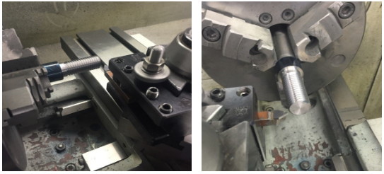
1. For this practice exercise for threading, you will need a piece of round material, turned to an outside tread Diameter.

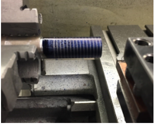
Thread cutting on the lathe is a process that produces a helical ridge of uniform section on the workpiece. This is performed by taking successive cuts with a threading toolbit the same shape as the thread form required.
The hole to be reamed with a machine reamer must be drilled or bored to within 0.010 inch of the finished size so that the machine reamer will only have to remove the cutter bit marks. Use plenty cutting fluid for reaming.
Reamers are used to finish drilled holes or bores quickly and accurately to a specified sized hole and to produce a good surface finish. Reaming may be performed after a hole has been drilled or bored to within 0.005 to 0.015 inch of the finished size since the reamer is not designed to remove much material.
To cut a correct thread on the lathe, it is necessary first to make calculations so that the thread will have proper dimensions. The following diagrams and formulas will be helpful when calculating thread dimensions.
Item Specifications · Thread Form. 60° Inch UN · Thread Form. 60° ISO Metric · Insert Style. Partial Profile (Non-Cresting) · Hand of Insert. Right-hand.
11. Take a scratch cut on the part without cutting fluid. Disengage the half nut at the end of the cut, stop the lathe and back out the tool using the cross feed. Return the carriage to the starting position.


 18581906093