
Horn Introduces Dual Coolant Tool Holder for 224 Indexable Insert Grooving - cutting tool holder carbide insert
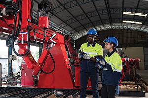
When working with an automated or robotic welding setup, accurate positioning is even more critical. “Automation requires very precise placement of parts, so that the welding robot or the torch is going to come to the same spot every time with a controlled arc, with wire position and wire angle,” says Kelley. “A manual welding situation where a human is manually adjusting things and is more flexible. Manual positioners do not have to be as precise as ones used for automation.”
Easily access valuable industry resources now with full access to the digital edition of Canadian Metalworking.
“A proper fixture should stop and locate stock at accurate angles while allowing adequate space for the welder to operate comfortably and efficiently,“ says Pam Farley, marketing manager for Strong Hand Tools. “A fixture can also elevate stock to create additional welding clearance, and set the structure at a uniform, level height. Fixtures should be designed with possible heat distortion problems in mind and work to minimize those effects. A fixture should be designed, at the outset, with a plan for the removal of the welded piece. Clamps, and clamping elements, should be able to easily swing out of the way for easy welded part removal by sliding off the table or lifting from the top of the work surface.”
Easily access valuable industry resources now with full access to the digital edition of Canadian Metalworking.
There is no escaping it— solidly clamping parts that you need to weld will ensure that these parts will not move unintentionally and be properly welded. Having pieces of metal move while heat is being applied is a recipe for disaster. Proper hold down of parts to be welded means they can be positioned accurately to make the weld successful.
A solid base and good clamping gear will bring success to any welding operation. PHOTO COURTESY OF STRONG HAND TOOLS
“The positive attributes modular fixturing brings to any welding operation is adaptability and repeatability. Adaptability enables a shop to take on a wide variety of jobs without having to create a specialized jig every time,” says Farley. “This is especially useful for short production runs or prototyping jobs where a dedicated jig and fixture will be quickly rendered obsolete by a design change. Repeatability refers to the basic requirements of any jig and fixture to hold work in a consistent and repeatable manner piece after piece. A modular fixturing system allows the welder to react quickly for customer retention, and modular fixturing provides the means to continue generating revenue from the one investment in the fixturing system. Also, the universal system can be torn down and stored away when not in use, freeing up valuable work space in the shop.”
When choosing an approach to fixturing there are basically two streams one can choose, modular or customized. In a nutshell, modular lets you adapt standard fixturing tools to suit any situation. Customized is a set fixturing solution that will be excellent for one part and that part only.
Easily access valuable industry resources now with full access to the digital edition of Canadian Fabricating & Welding.
A lot of shops considering automation already have ready access to CNC cutting machines and simple drilling or turning capabilities. In these cases modular fixturing simplifies the fixture design and fabrication process because fixtures do not need to be built from the ground up. Each custom part tends to be smaller and requires less machining because the modular fixture already addresses one or more dimensions requiring adjustability or flatness.”
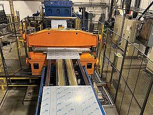
Modular fixturing is built to high tolerances to provide accurate holding in any position. “A modular fixturing system, such as the BuildPro Modular Welding Table line, is composed of reusable components so the user does not have to fabricate individual fixture elements every time,” says Farley. “These modular components are adjustable and universal. A good modular system includes the table, with a tabletop surface of highly accurate CNC machined holes (mounting holes), in a dimensionally accurate grid pattern, for the setup of clamps and components at any point along the tabletop to accurately hold stock. The modular BuildPro tables feature plates that can be added or repositioned to reconfigure the table length or width for odd shaped or oversized weldments.”
Easily access valuable industry resources now with full access to the digital edition of Canadian Fabricating & Welding.
Keep up to date with the latest news, events, and technology for all things metal from our pair of monthly magazines written specifically for Canadian manufacturers!
“Modular systems can be integrated into automated welding processes, but the recommendation with higher-volume production is to use the modular fixture system as the physical framework for custom fixtures. For example, custom pins can fit into right angle brackets to hold punched sheet goods using indexing holes already designed from previous manufacturing processes.
“Automation often requires lower profile fixtures for better robot arm access. Automation also comes with a different mindset where the weldments are often smaller, and a desire to decrease cycle times requires fitting several parts onto the table at once. This means that fixtures need to be more compact in their design,” says Farley.
Keep up to date with the latest news, events, and technology for all things metal from our pair of monthly magazines written specifically for Canadian manufacturers!
Keeping the gap between the pieces to be welded consistent is also critical to completing a successful weld. “Fixturing is used primarily to minimize the gaps to improve the final welding quality,” says Reg Kelley president at Easom Automation Systems Inc. Controlling or minimizing gaps ensures the welding process is not being asked to fill large voids or gaps, notes Kelley.
In total 16 vises are mounted on a 4th modified axis in a 3-axis machine. Thanks to the use of the compact vise SCHUNK KSC mini, the workpieces can be processed in one set up which results in a strong decline of run through time.
Lincoln Electric is a one-source solution for all your cored wire fabrication needs. From cored wire, power source, fume management, collaborative robots and optimized waveforms, plus a best-in-class service network – we have you covered. Choose The Welding Experts®. Choose Lincoln. Book Demo Now!
Failure analysis as it relates to cutting tools is an often-overlooked path to improving a machining process. Of course, eventually all cutting tools will fail, but failure analysis will help to optimize the output of the operation. Failure analysis works by checking the condition of the insert at a predetermined number of pieces. The condition of the insert would be analyzed at these checkpoints. The condition of the insert would be compared to typical failure modes, a diagnosis would be determined and adjustments would be made to maximize productivity. All too often a machine operator will bring a fractured insert to the tool crib and request more inserts. Once the insert has fractured, there are no clues as to the reason for the failure.Often in North America, tool life is simply measured by the amount of cut time, the number of parts or the distance the tool travelled while removing material. The determinant to indicate when the tool has reached its life expectancy is often the load on the spindle, the surface finish on the part or in some cases catastrophic failure. This is unfortunate, as the performance of the tool could be greatly enhanced with the proper diagnosis and alterations.In Japan, it is common to set predetermined checkpoints to inspect the insert. This is helpful, because one can see what is happening to the insert and make adjustments to optimize the tool’s output. Once the other failure modes have been corrected, measuring flank wear can then be the determinant of tool life.As mentioned earlier all inserts will wear out. However the ideal wear pattern is flank wear. By checking the insert at predetermined intervals, it is possible to see how the insert is wearing. There are many different types of wear patterns classified in failure analysis. Ultimately these failure modes – flank wear, notch wear, crater wear, plastic deformation, built up edge, thermal cracking, chipping and edge fracture – are symptoms of a shortened tool life. If the symptoms are recognized early, adjustments may be made to reach the desired outcome of flank wear.Some of the symptoms of tool wear are:
It is useful to observe the visible signs on the insert. This illuminates common failure modes, and helps to correct those failure modes that lead to under-performing cutting tools. The desired outcome is standard flank wear on the insert.Flank WearFlank wear is normal. All inserts will eventually wear out. The best situation is to have the insert wear through flank wear. However, premature flank wear is not desired. The ideal situation is when it is possible to extend the life of the insert before flank wear causes failure, thus minimizing cycle time.The cause of flank wear is generally abrasive wear caused by the cutting speed, the hardness of the part, or a hard skin on the material being removed. Flank wear occurs when abrasion erodes the coating and eventually the substrate. The ideal flank wear is an even progression, making the process predictable.Some remedies to reduce flank wear are to select a grade that has more wear resistance. As a quick fix, one could simply slow the cutting speed, thereby increasing tool life but sacrificing cycle time. Of course, the best solution is to keep cycle time as short as possible. The long-term solution is to select a better grade.Notch WearNotch wear appears as a notch on the insert, generally at the depth of cut level. It is an oxidation at the depth of cut. This oxidation is caused by high temperatures and the presence of air. Tungsten and cobalt, the main ingredients in carbide inserts, form weak oxide films during oxidation.To remedy notch wear, select a more wear resistant grade. Generally inserts coated with Al2O3 which can help prevent oxidation of the substrate. As a quick fix one could increase the lead angle on the tool. This would ease the insert into the material and would also provide “chip thinning”. Another remedy would be to vary the depth of cut. In this way, the insert is not always cutting at the same depth of cut point. A variation of that method would be to make your first pass a taper and your next path a straight cut which would produce a constantly changing depth of cut.Crater WearCrater wear appears as a diffusion between the insert and the workpiece material. It occurs when enough thermal energy is created to enable the exchange of atoms across the tool-workpiece interface. The amount of diffusion depends on the chemical affinity between the two. For instance, tungsten and steel have a high chemical affinity. Effective remedies include using a lower cutting speed, or choosing a grade with more wear resistance. For instance, an Al2O3 coating helps to prevent diffusion and reduces crater wear.If you begin to lose chip control, check for crater wear because excessive types of this wear tend to change the edge geometry of the insert. Plastic DeformationCompression and heat, combined with high feeds and hard work materials, cause deformation of the insert edge. As edge deformation increases from the pressure, temperatures continue to rise, contributing to further deformation.Look for the edge to lose sharpness and bulge out when this happens.A quick fix is to reduce the speed or feed rate. But for long-term productivity, a more wear-resistant grade is key. Built-up edgeA built-up edge is when the workpiece material gets welded to the cutting edge. This usually occurs when cutting temperatures are too low. Additional chip flow is needed to avoid it. The remedies to this are to increase the cutting speed, and select a more positive insert geometry. Another remedy would be to increase the coolant flow to add lubricity. In the case of aluminum, use a polished insert to increase lubricity. In gummy steels, use a smooth, slippery coating.Thermal CrackingThermal Cracking is caused by abrupt temperature changes. A quick remedy is to turn the coolant off completely, or by drenching the tool in coolant to stabilize the temperature. Using a tougher, more wear-resistant grade is also an effective solution. When doing interrupted cutting, always run without coolant. ChippingChipping occurs when the insert edge breaks rather than wears. The fatigue associated with chipping is generally caused by temperature and force fluctuations. It usually means that the application is too demanding for the selected insert.To remedy this, it is necessary to select an insert with a stronger cutting edge. Also, try a tougher, more shock-resistant grade of carbideEdge FractureEdge fracture happens as a result of the other wear types. Remedy check all the cutting data and setup to consider what it might be. Once the edge fractures, the reason is unknown. Ideally, you want to check the insert before a fracture occurs to determine why such an incident might happen. The likely remedies for this are to reduce the feed rate, reduce the cutting speed, or select a tougher grade.John Mitchell, MBA, is the General Manager of Tungaloy Canada.
When making many thousands of the same part, or if it’s a very complex part, sometimes a customized fixturing solution will make the most sense. “Custom fixturing works best to fit any unusual structural shapes,” says Kelley, noting that custom solutions are often used for curves or different shapes. In an operation that produces continuous production runs of oversized, heavy, bulky, specialty structures that cannot be fixtured using off-the-shelf universal components a custom fixture is the only solution. Dedicated fixturing may be the best option for long-term contract work, in which engineering changes are infrequent and tight tolerances are required.


 18581906093