
Norton Winter Paradigm Plus Diamond Wheels feature new grain tech for high
Edgecam has been through something of a renaissance and some of the updates made in the last few releases show that it is one of the more advanced and current tools in the Hexagon armoury
Edgecam has been through something of a renaissance and some of the updates made in the last few releases show that it’s one of the more advanced and current tools in the Hexagon armoury.
Vertical lathes (VTLs), especially large ones, are used to manufacture critical parts in most heavy industries including aerospace, wind, oil-and-gas, and many more. The bearing that supports the table and workpiece has a direct impact on the tolerance and surface finishes that a VTL can produce. This report will help readers understand how precision tapered cross-roller bearings (TXRs) used to support the VTL tables impact cut quality of the parts processed on these machines. (See Figure 1.)
The error motion of the VTL table bearing contributes directly to the runout and surface finish of the workpiece. It manifests as a table tilting error, a characteristic that directly impacts workpiece runout and face flatness (see Figure 18.) The tilt amplitude is the bearing error multiplied by the height of the cut/measurement above the bearing centerline. Tilt error is minimized with TXR bearings because the roller and raceway geometry are controlled beyond ISO and ABMA standards. It is important to remember that the altitude of the cut test does have an impact on the results.
VTLs are used in a wide variety of industries to machine an extensive range of parts, with tolerances and surface finish requirements that vary greatly. Even parts with lower precision requirements still need a table bearing with precision-class tolerance. Unfortunately, the bearing features controlled in the ABMA
Turning inserts are made from very hard materials (such as tungsten carbide) with the goal of cutting cleanly through the workpiece material. Both the insert and the workpiece material have a profound impact on the roughness (Ra) and visual appearance of the finished surface of turned parts, but for the scope of this report it is assumed that the insert is correct for the workpiece material.
For those that are unfamiliar with this, it involves using a CNC-controlled head that deposits molten metal in layers, just as any 3D printer would, either by using a rod-fed process similar to welding or using a powder feed and plasma torch.
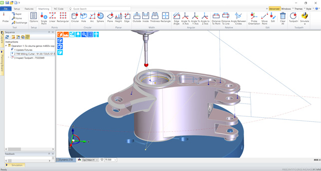
To begin, you start with an ‘Insert Tombstone’ command and set up the usual machine options, clearances and so on.
This is focused, for the time being at least, on button-style turning tooling, which allows you to cut both directions on the spindle axis. When combined with Waveform’s efficiencies, the end result is a set of operations that maximises material removal with less wear on your inserts and a more efficient operation. Set-up is, as you would expect, pretty simple, as it’s focused on maintaining engagement angle, speeds and feeds.
Hexagon is applying its knowledge of machine control to the additive world, and in particular, DED machines
The last update to Edgecam that we’re going to look at is a new set of functionality built into Edgecam to add support for DED (Directed Energy Deposition) additive manufacturing.
As a result, Hexagon has adapted the most suitable operations from Edgecam to enable programming of DED set-ups, adding in those key parameters that need to be fed to the machine alongside movement coordinates, including laser power, gas and powder/rod control, speeds and so on.
Oil circulation is the most common lubricating method for VTL table bearings because it helps to maintain a lower and more uniform bearing temperature, especially at higher speeds. Closed loop circulation systems are used to filter and cool the oil to maintain the temperature around 75°F (25°C.) Oil viscosities range from ISO VG 46 to 68. It is customary to inject the oil in multiple locations around the post/shaft in between the inner rings, typically 8 to 16 injectors depending on machine size (see Figure 7.)
Runout is the displacement of the surface of a rotating object (see Figure 16), while error motion is the displacement of the axis of rotation (Figure 17.) Although error motion is what matters most in this application, assembled bearing runout is the traditional method of validating whether all the component tolerances are met when the bearing comes together. Error motion is typically much less than the bearing runout.
Sizing and tuning hydrostatic bearings properly is very difficult, because friction power grows exponentially with speed that is limited by heat. Typically, hydrostatic bearings have speed ratings 50% less than will be possible on a table of the same size supported by a TXR bearing.
Most VTLs have four degrees of freedom, three linear (X, Y and Z axes) and the table rotation (C axis.) The cross slide provides the “X” and “Y” motions, the ram provides the “Z” motion, and the table performs the “C” rotation. The reason these lathes are referred to as “vertical” machines are because the workpiece rotates about the vertical “C” axis when material is removed by the turning process.
Using the concept of masks, it’s possible to hard-code in options and variables within a command, and then ensure that only the options that the user needs to change are exposed. If you’re looking at this as a means to clearly establish corporate standards and best practices for users, you begin with a single seat, make all of the customisations (a task that has to be performed ‘in product’), then export a theme to be used across the whole user group. This is also a great way of GUI simplification for occasional users.

The advantages of the TXR bearing over other bearings of similar design and other bearing configurations are why it has become the standard for VTL table bearings. Their compactness and small cross-section provide a simplified table design together with a maximum running accuracy. Their wide, effective spread ensures high stability and maximum rigidity. Low starting and running torque reduce heat generation to yield good speed capability.
From its origins as a 3-axis focused production CAM system, Hexagon’s Edgecam has come a long way in recent years.
Because of the unique requirements of this application, the VTL table bearing manufacturer is compelled to control internal geometry to minimize the assembled bearing error motion, not the runout. (See Selecting TRBs for Machine Tools: Going Beyond Tolerance Standards, Part 2.)
Introduced back in 2014, Waveform is Edgecam’s take on trochoidal roughing, whereby the CAM system attempts to maintain a constant load between cutter and stock. What varies between each vendor is how they deliver this capability.
Essentially, you pick the form you want to build and define the parameters.The system will build up that form using layers of parallel laces and boundaries. You have control over the order of those operations and can add in variations, such as rotating the lace orientation by 90 degrees per layer.
Today’s system looks as fresh and modern as ever and its emphasis remains on making life easy for the machinist. What’s changed, perhaps, is how the system goes about meeting that not-inconsiderable challenge, as well as the range of production techniques that it now supports.
For 2019, the workflow has been overhauled to make the process both easier and more intelligent. It’s an additional licence requirement, but if you’re carrying out this type of work, that’s probably to be expected.
The list of the characteristics that make TXR bearings very attractive for VTL table bearings includes:
To best explain how TXR bearings influence the performance of a VTL let’s start by providing a brief overview of the application, including a rundown of the VTL’s major components and sub-systems, along with a basic explanation of “turning,” the primary operation performed on these machines.
There are a number of benefits to this approach, ranging from more efficient toolpaths to a decrease in cutter wear (and reduced cost as it focuses on cheaper carbide-style tooling), as well as less heat build-up and machine wear.
On the subject of Hexagon, the move to rebrand all of its CAM systems under the parent company name will surprise a few, particularly considering it’s only relatively recently that some of them took on the Vero name – but this change was inevitable.
Of course, this means that your internal inspection processes might need to adapt to having your CNC machine effectively ‘marking its own homework’, but given confidence in your machine tools, there are some serious time savings to be had here.
Eric Faust is an Application Engineering Specialist with The Timken Company. Contact him at [email protected], or via LinkedIn.
Then you start to add in the parts you want to machine. The process uses a common datum to position parts; the idea here is that you do all of the programming for each individual part, then have the system work out how to link multiple instances or different parts, in terms of consolidating common operations (by plane/datum or to minimise tool changes).
The values of these parameters are based on the material, insert, and the desired quality of the cut (rough vs finish.) The geometry of the insert and whether cutting fluid is used also factor into determining these values. The quality of the cut is judged by the runout, surface finish roughness, and visual appearance of the workpiece (see Figure 9.) Cutting parameters are not addressed here, but assume that they are properly selected for workpiece material and cut type.
Rollers have free-floating polymer separators situated between them to prevent direct contact during operation, as seen in Figure 15. Because they are free-floating and lightweight, they help to minimize the starting and running torque of the bearing. This is part of the reason that TXR bearings have the speed ratings for their size, capacity, and stiffness. The TXR bearing is “separable,” meaning the components are shipped separately and the bearing is assembled during the table installation (see Figure 14.)
The thrust TRB design is a close second because it has comparable tilting stiffness and typically a higher load-carrying capacity. But it requires a second set-up bearing, which make the design more complicated and the overall machine cost higher. Minimizing the height of the table is one of the greatest advantages of the TXR because it makes for a less complex and more compact design than a table with a 2-TS or a thrust bearing (TTHDFL or CRB) with a TS set-up bearing (see Figure 11.)
It’s also good to see that the system is expanding its reach to cover both new machining technologies (such as those fancy cutters from Sandvik) as well as exploring the future promise of DED additive processes.
There are a number of benefits to this approach. First, those originating part programmes are live-linked, rather than inserted as a copy, so any edits to underlying operations can very quickly be propagated to your tombstone set-ups. Second, it means that common operations can be collated and split out as individual sub-routines, such as drilling cycles.
Eric Faust is an Application Engineering Specialist at The Timken Company, providing sales and customer support with technical bearing expertise and helping to resolve customer performance concerns.
Finally, it also allows post processors to be rationalised. It may be the case, for example, that each part on your tombstone is set up for a different machine tool. Now, Edgecam will consolidate these and ensure that every operation is ready for your machine at hand. It also makes light work of moving jobs to match your machine tool capacity.
EdgeCAM Inspect allows you to programme in inspection routines as well as building more intelligent feedback loops where needed
As ever, the Edgecam interface is up-todate with modern standards, but continues to offer the customisability that many users have come to expect and regularly use. What’s interesting here is that rather than just being a case of configuration – the moving around of toolbars and icons, for example – users now have more granular control over how the system presents commands, options and operations.
Alongside the big headline updates, there are always a number of smaller updates that are just as key, particularly for existing users, but which are hard to categorise.
The system will then generate the G-code to drive your probing process. The machine then performs the operations, captures the data and, via Hexagon’s NC Gateway, returns it to the machine as a report that can be used for standard inspection or perhaps as the basis for on-machine verification and adaptive set-ups.
A TXR is effectively double row bearing where both rows reside in the same axial location. TXR’s are referred to as “cross-roller bearings” because alternating roller’s apex is oriented in the opposite direction of its two adjacent neighboring rollers forming a cross or “X” pattern. The most common available configuration is the TXRDO and consists of a double cup (outer ring with two raceways), two inner rings, a roller set, roller separators, and roller extensions (see Figure 12.)
There are also a couple of new operations brought across from elsewhere in the Hexagon portfolio. A good example here is the lace cycle. Again, this is a pretty common or garden operation in the machining world (typically for more complex surface machining), but when flipped into deposition operation, it makes huge sense, because it allows the user to programme stock build-up using a form and parallel runs of material, combined with an exterior boundary (or vice versa).
The bearing is one of many components on a VTL that must work nearly flawlessly to performance requirements. It is important to note that although the bearing is one of the primary contributors to the runout, surface finish, and visual appearance of the workpiece there are other factors, outside the bearing, that also can impact the quality of the cut. The rigidity and natural frequency of the ram, headstock, cross slide and base need to be taken into consideration as well. The workpiece material inserts and cutting parameter along with the workpiece material also impacts the quality. Finally, any external vibrations that can be transmitted to the table post such as motors, pumps, compressors, gear drives, etc. will also show up in the table error motion signal.
A body cut turns the OD or bore of a workpiece along the Z axis. A face cut turns the top of the workpiece in the X-Y plane. The three primary turning parameters are the cut depth, surface speed, and feed rate. The cut depth is how deep the insert nose is plunged into the workpiece; the surface speed is the linear speed of the cut, or how fast the tool is moving through the workpiece; and the feed rate is how far the tool indexes for every rotation of the workpiece, and it is specified in inches/rev or mm/rev.
The roller small ends are drilled at the centerline and a polymer insert is pressed into the hole. The insert is referred to as a “roller extension” and prevents the roller from falling away from the outer race (rib) during assembly (see Figure 15.) When the bearing is in operation, there is an air gap between roller extension and the inner race when the large end is seated properly.
A good example is the work done to reduce the number of checks that the system makes when you make certain edits to your operations. Previously, edits would force Edgecam to run its full set of checks to ensure the part is as should be.
Figure 2 highlights the major components and sub-systems of a VTL that includes a cross slide, headstock, ram, table and CNC controls, and chip removal system see. Under the guarding and sheet metal covers there is a table drive, lube oil circulation system, tool changer, and the base-frame that supports and integrates all these components. (See Figure 2.)
It is worth mentioning that the size of a VTL is based on the table diameter and/or the maximum size workpiece that can be turned on the machine. Typically, the VTL model number is based on the table OD in centimeters, millimeters, or inches. Examples are the Phoenix VTL 144 seen in Fig. 1, the Honor model VL-160CM VTL in Fig. 2, and the You Ji Model VTC1000ATC+C in Fig. 3.
The rollers are designed with an L/D less than 1.0, meaning that their length is less than their diameter. This is required to achieve the 45° included angle and helps to keep the bearing section compact with large, effective rolling centers. The greatest advantage of this design is the high tilting stiffness that the effective spread yields, as illustrated in Figure 13.
There are two turning operations that are common to all lathes: the face cut and the body cut (see Figure 8.)
It is important to understand that when measuring the tilt error motion of the table there are two components to the error motion: 1) the synchronous (repeatable) and the 2) asynchronous (non- repeatable), as shown in Figure 19. The synchronous tilt error motion contributes mostly to the runout of the workpiece where the asynchronous is primarily responsible for the surface roughness. The visual appearance of the surface finish is a function of frequency/modulation of the tilt error motion.
Before focusing on the TXR bearing, let’s review the bearing options for supporting VTL tables found in machining operations today, along with their advantages and disadvantages.
Although there are other options for VTL table bearings, the TXR is by far the most popular and common for these reasons. It ranks highest in almost every category, as shown in Table 1. With ongoing efforts to continually improve its performance, it will most likely remain the leading choice for bearings to support tables in VTL applications for years to come.
Waveform has expanded beyond Edgecam, in fact, and is now available in the majority of Hexagon’s milling systems, including Alphacam, Edgecam, Surfcam, VISI and WorkNC. What’s new for the 2019 release is that the team has also integrated this capability into the turning environment.
Figure 4 is a typical table drivetrain that consists of a variable-speed motor connected to a gear reducer that drives the table carrier assembly via a precision rack-and-pinion gear set. Note that the bull gear is fixed to the table carrier housing that is supporting the bearing outer ring, thus rotating the bearing outer ring.
The thickness of the shim pack determines the preload setting. TXR bearings are preloaded to achieve the speed, stiffness, and runout requirements of this application. The outer ring clamping plate ensures that the double outer ring is securely fixed to the carrier, and it is not uncommon to the have the bull gear integrated into this plate.
There is a full set of inspection tools in the Edgecam environment, with a probe tool store supporting Hexagon, m&h and Renishaw probes. The tools automate some functions, such as automatically finding matching features such as holes on a single PCD, for example, and automating inspection set-ups.
Most VTL tables mount to a carrier assembly that houses the bearing, as shown in Figure 5. The table is typically slotted to accommodate jaws or chucks for clamping down the workpiece to be cut. Carriers may also incorporate pallet changers to allow entire tables to be automatically loaded and unloaded onto the machine, to reduce setup time. The type of table and maximum workpiece size determine how much weight the TXR bearing is required to support.
The actual CNC mechanism that moves these DED heads can vary from pretty standard CNC machines (either specially built or retrofitted), gantry-based systems or industrial robot arms.
Using the gateway, it’s also possible to build up links between Edgecam, inspection and a feedback loop. To do this, you would set up inspection entities and operations, then create the inspection cycle which incorporates an element of calibration.
What has also become clear is that there’s been some serious reorganisation of how this range of tools is developed and I’m told that the company’s internal development teams are now organised according to competency rather than product, so we should start to see more meaningful updates across all the key Hexagon machining products as we move forward.
These are specially shaped inserts, so the Edgecam team has had to do a fair bit of development to enable its programming to not only support their use, but also to ensure that their advantages are properly supported (for example, gouge-protecting the inserts and various lead in/lead out strategies specific to this tooling). In addition, a new finishing concept, Up-Turning, is now available to enable highproductivity finishing with the use of these specific tooling inserts.
The carrier assembly in Figure 6 consists of the carrier (housing), post (shaft), TXR bearing, outer ring clamping plate/bull gear, preload clamping plate (spigot), preload (shim) spacers, and the table. Because the table bolts to the carrier on most VTLs, the outer ring of the bearing rotates with the carrier and the inner rings (cones) are mounted to the post (shaft), which is attached to the machine frame and stationary; this is referred to as a “dead shaft”.
For existing users, there’s plenty to get stuck into in the 2019 release. For those working at the more complex end of the spectrum (such as mill/turn and 5-axis), it’s clear that there has been a good amount of work done to make tools more efficient, both during programming time as well as on the machine.
VTL table bearing options can be divided into two categories, roller element bearing and hydrostatic bearings. Hydrostatic bearings are typically used on larger tables when roller bearings of sufficient accuracy and/or load-carrying capacity are not available (see Figure 10.) Like any other bearing type, hydrostatic bearings have advantages and disadvantages.
There is huge potential here, assuming the correct machine tools are in place, to combine these additive tools with more traditional machining. We’re certainly seeing a move towards finding new ways to integrate additive deposition and traditional removal of material more closely; for example, alternating between deposition layers and machining passes to improve accuracy, reduce post-processing and better handle thermal issues that arise in such processes.
While this can be beneficial, the reality is that there is a certain class of edits where it’s not necessary for the whole programme to be checked; for example, a change in coolant. This might sound like a small change, but when you consider the iterative nature of part programming (and particularly optimisation), time eliminated from the process quickly mounts up over the course of an average working week.
TXR bearings range in size from 11 in. OD (279 mm) to 111 in. OD (2819 mm.) Sizes above 111 in. (2819 mm) are possible, up to 3.4-meter OD currently. With table ODs that are 40 to 60% larger than the bearing OD, it is possible to use a TXR bearing in a VTL with a 28-foot (8.5-meter) table.
This is what has happened with Sandvik Coromant’s CoroTurn Prime tools and inserts, which have been developed to allow cutting in both directions on the spindle axis.
19.2 or ISO 492 do not meet all the requirements for this application. (See Selecting TRBs for Machine Tools: Understanding Tolerance Standards, Part 1.)
This has meant that you can now insert inspection processes into your workflow more directly and remove some of the bottlenecks typically found in industrial workflows; for example, moving parts to the inspection department and back again, with all of the repetition this entails, as well as the potential for set-up errors.
Having detailed where the TXR bearing is located in the VTL, and how it is mounted, let’s address the basics of turning – which is the primary operation of all vertical lathes.
Turning is how material is removed from the workpiece on all lathes, horizontal or vertical. What makes turning fundamentally different from milling and grinding (which removes material from a stationary workpiece with a rotating tool) is that turning removes material from a rotating workpiece with a stationary tool (insert), as shown in Figure 8.
Another key focus for the latest set of releases is greater support for tombstone machining. While Edgecam has supported tombstone in the past, where multiple parts are loaded onto specialised fixtures to enable rapid production, the workflow involved was complex, particularly if you were working across multiple different parts and at the same time trying to maintain a rationalised tooling library.
The drawbacks for hydrostatic bearings are their cost, complexity, and speed. Hydrostatic tables are significantly more expensive, both up front and to operate, because they require a hydraulic power unit and a chiller to manage the heat generated.
Speed capability is an important characteristic of the table bearing. Maximum table speeds range from 800 rpm on smaller machines to 50 rpm on larger machines. The limiting speeds of TXR bearings align nicely with VTL speed requirements.
In the context of Edgecam’s technology, rather than changing speeds and feeds, Waveform adjusts the toolpath to maintain the tool engagement angle (the portion of the cutter in contact with the stock) to within a workable, optimal range (between 20% and 30%) and thus ensures consistent material removal.
If you’re not familiar with how the CAM industry works, it’s often the case that a tooling vendor will develop a new method of removing material (or a variation thereof) and then must wait for CAM vendors to provide a way to programme parts to take advantage of that tooling. Conversely, the CAM vendor needs to ensure that its leading edge customers can take advantage of the latest innovations in tooling design.
Preloading of the bearing is accomplished with a shim pack that is captured between the shaft face and the preload clamping plate, as shown in Figure 6. This is referred to as a “spigot design” because it looks like a water spigot, with the “nozzle” protruding and seating on the lower inner ring (cone) backface. The shim pack also may be positioned between the lower inner ring backface and the clamping plate. The location is a matter of preference by the machine builder, either configuration is acceptable.
For the last two or three versions, Edgecam has offered inspection capabilities, as you would expect, based on Hexagon’s PC-DMIS.
Hydrostatic bearings accommodate larger tables than even the largest rolling element bearings available will do. They also have higher load ratings than rolling element bearings, and slightly higher accuracy.
Also, as should be obvious, this approach relies on many of the core competencies of any CAM system, with the key difference being that the machines are typically depositing material, rather than removing it from a billet or a casting.
Basically there are five VTL table roller bearing configurations that have been used to support VTL tables, including the TXR bearing, thrust TRB, thrust cylindrical roller bearing (CRB), ball bearing (BB), and a cross-roller CRB (CXR.) Comparing the characteristics of each of these bearing types makes it obvious why the tapered roller XR is the most popular choice for this application (see Table 1.)
Edgecam 2019 – Since Hexagon took over the Vero portfolio, things have moved on apace. We take a look at the latest updates to its production machining-focused system


 18581906093