
Pete Kalamaris Accused of Being “Navy War Hero” Liar Liar Pants on Fire - china cnc lathe insert
Even without raising throughput rates in the cells, the shop reported it achieved savings of $80,000/year in tooling and tool-servicing costs. The only edge failure mechanism now is predictable flank wear, with zero rupture in more than a year.
In today’s complex micro machining world, it is not uncommon for 30 to 60% of a company’s tools to be custom, said MacArthur. About 60% of RobbJack’s business is custom. “We have the luxury of seeing some pretty amazing projects,” he said. RobbJack will re-create customers’ applications in its lab, run test cuts, then report back indicating the proper tool and process parameters.Meanwhile, Paquette said maybe 15–20% of Richards Micro-Tools’ portfolio is engineered solutions. Such projects “don’t happen overnight,” instead developing over years as a relationship with a customer is built.
With cutting diameters from 0.06″ (1.5 mm) down to 0.02″ (0.5 mm), they are made to process “super-tough material like Invar or any of the stainless steels, he said. “It was kind of a surprise when we put it out. We knew it would do well in precision tool and die applications, but it turns out it’s being used across multiple markets, such as medical and aerospace.”
At Kyocera, a range of special end mills addresses medical industry demands, said Wilshire: “We do step drills to try to save cycle time,” aiming to process a part in one pass.
Extraordinary throughput gains can be achieved by dialing in the right process and materials, as Paquette illustrated in a recent case. A Richards client machining a feature into spools of laminated plastic material used in the printing industry would get about 200″ (5.1 m) of material before the cutter had to be changed. By refining a corner-radiused end mill with a diamond-like coating and switching from an upshearing cut to a downshearing cut, Richards’ tooling produced 800% more linear footage. The 2018 Richards catalog includes two new levels of diamond coating.
Proprietary materials like aerospace stainless steels typically require proprietary coatings to increase tool longevity and foster chip evacuation by maintaining lubricity in drilled holes, according to Kevin Jackson, round tool product specialist for Kyocera. Coatings like Kyocera’s Megacoat series are applied at thicknesses based on tool diameter.Where coatings won’t really help, Negron said, is in the super-micro world of tool diameters under 0.008″ (0.20 mm).
“Now we’re down to 1 mm for two-flute drills of 8×D or 15×D.” These drills are particularly geared to aerospace materials like 17-4 PH, titanium and Inconel, said Brian Wilshire, technical applications manager for Kyocera.
Meanwhile, Kyocera’s coolant-through 10×D Hydros drills will soon be joined by 5×D and 7×D versions. “We initially came out with drills down to a 3 mm cutting diameter,” Negron explained.
The primary reason for the big improvement in cutting-edge security is the Hex-Turn insert’s stronger geometry, according to Ingersoll turning product manager Ed Woksa. “On the one hand, the insert has a 45-degree lead angle that thins the chip and reduces notch wear,” he explained. “On the other, the hex shape is closer to a true round, intrinsically the strongest shape due to the absence of stress-raisers.”
Of course, micro tools are only as accurate as the equipment and software that produce and guide them.
“Operations in cells must run in lockstep,” said Ingersoll’s Konrad Forman, “so it’s doubly important there to achieve longer, more predictable edge life on the tooling. “Take any failure root-cause other than gradual wear as a wake-up call to find a better tooling solution, even on a loose machine or any other in unfavorable condition.”
The improvement stems mainly from the tangential orientation of the inserts in the cutter, Ingersoll’s Konrad Forman explained (see Fig. 2). “Unlike conventional radial cutters, the inserts in a tangential tool lie flat in the pitch circle, presenting the insert’s strongest cross section to the main cutting vector and converting shear stresses to more manageable compressive forces.”
“Our focus outside the general catalog line … becomes a threefold process to improve performance,” explained Paquette, honing the proper mix of materials, geometries and coatings “that do not diminish what we’ve done with our cutting tools and our geometries.”
The switch was from 80-deg rhombic inserts to Ingersoll Hex-Turn inserts. “I found them the day they hit the market because I regularly surf the ‘net for new solutions we can use,” said Jerry Busche, vice president.
The company’s tools process everything from platinum to PEEK (polyether ether ketone) plastic, he said. While Richards has been a pioneer of micro milling—having always offered end mills at 0.005″ diameter and always employed microscopes in their facilities to evaluate their tools—Paquette noted that today’s tool repertoire includes diameters down to 0.0005″ (0.013 mm).
Of course, cutting-edge security matters a lot in every machining operation, but never more than in synchronous machining cells or carousel arrangements. Sudden tool rupture or edge breakdown at one operation can affect the entire process. Moreover, the risk of failures is often the main cause of extra operator attendance.
Positive rakes and helical cutting edges on the inserts combine to create a smooth cleaving action, all leading to a much more secure process even on a loose machine.
Running 24/5, Busche uses seven two-lathe turning cells to produce 2.75 million/year automotive ring gears in a 400-person shop. Operations there include OD turning, ID turning and facing. As any Tier 2 automotive supplier knows, this is a very competitive business, turning on pennies per part and rock-solid delivery.
Solid-carbide micro cutting tools about the diameter of human hair or smaller—some producing parts visible only under a microscope—are making a huge impact on manufacturing highly advanced electronics, automotive and aerospace fuel injection systems, and medical instruments and implants.
Coatings tailored to match the maximum cutting temperatures of many unique ferrous and nonferrous metals and carbon fibers allow higher working temperatures and can increase cutting speeds by up to 20%, noted Kyocera’s Negron. Experiments with PVD coating equipment abound to find the best process mix of gas, temperature and deposition rates.
At RobbJack, every micro tool offered in increments of 0.0002″ (0.005 mm) is available in titanium nitride, titanium carbon nitride, AlTiN and the newer diamond-like carbon, MacArthur said. When cutting heat-generating metals like stainless steel or nickel alloys, AlTiN is the ideal choice, he noted, since it forms an aluminum oxide heat shield that keeps heat from going into the tool.Ultimately, coatings produce cost savings, said Richards’ Paquette. In a medical production scenario, for instance, an enhanced-performance tool can process 200″ of material with parts having to be checked only 10% of the time.
Many managers in manufacturing operations regard these types of failures as unavoidable on tired equipment, or they keep cutting back on parameters and stepovers, hoping to find some stability.
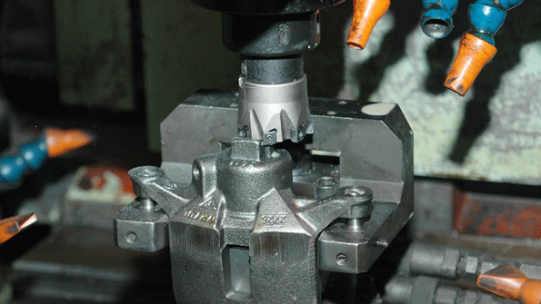
The most challenging operation is milling out the main yoke slot. Previously, this had been done by roughing in a multi-pass cycle with a conventional zero rake cutter using eight square inserts, and finishing with a separate tool. Sudden edge breakdown during roughing was an accepted part of the production process, even after radically reducing stepovers to avoid pounding. Ironically, the lighter stepovers required more passes, causing work hardening that punished the tool even more.
For proper machining, Boss stressed using a high-accuracy toolholding system like Horn USA’s Fahrion and a spindle speeder, if necessary. Maintain correct cutting speed, radial and axial depths and feed per tooth, and clear chips during operation with proper placement of compressed air or coolant to avoid double cutting chips, he advised.
Kyocera Precision Tools Inc. (Hendersonville, NC), which has “historical strength in drilling,” has been having success with its Titan AX three-flute and upcoming five-flute micro mills on 6-mm shanks, said Round Tool Product Manager Joe Negron. “With three flutes, you always have a cutting tooth engaged,” he said. Five-flute mills, already proven to allow higher-speed milling with Kyocera’s indexable tools, will bring that functionality to the company’s solid round tools.
To protect these valuable tools, Boss said pre- and post-use inspection are as important for preventing breakage as adhering to proper usage parameters. Before use, he advises using a micron accuracy tool presetter with live-view camera and automation to inspect for runout and form. This not only affirms tool geometry and proper runout, but achieves tool-length offset with no touch-off required.
Meanwhile, current CAM software maintains equal chip load whether the tool is in a turn or corner, Negron said. Many customers preview their software by programming, for example, a high-speed milling routine, and making sure the process is optimized “no matter where you are in the part.”
Also aiding smoother cutting was the higher insert count in the cutter, made possible by the tangential design. The new 2-inch tangential S-MAX has seven inserts, versus four in the previous 2-inch cutter. “Under the same parameters, more inserts means lower cutting forces on each one,” Forman explained.
One key to machining success “is the equipment and how it is clamped,” Kyocera’s Negron said. “The best clamping is heat-shrink. End users are concentrating on buying very good machine equipment that has excellent clamping.”
Old, ‘loose’ machines are torture for cutting tools. They create an ideal setting for chatter to start, which can create excessive impact forces on the tools leading to sudden tool rupture.
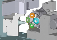
Akebono produces the brake calipers in an auxiliary machining cell that feeds a traditional transfer line (see Fig. 3). Because the whole operation is synchronous, there’s no way to speed up a single operation without unbalancing the whole line.
Net Surfing to Longer Edge Life — At Busche-CNC in Albion, Ind., a simple retooling de-bottlenecked the rough turning operation for difficult-to-machine wrought 5130 and hardened 4140. Previously, cutting edges cratered after an average 20 pc on the 5130; toolbars snapped every other day. The Ingersoll Hex-Turn inserts improved edge life nearly 10 to 1, and eliminated completely the unpredictable, cutting-edge rupture and all the hazards and disruptions that followed.
Richards’ Paquette said that most tool companies have proprietary software specific to their CNC grinding machines that models optimum tool designs and performance. Two years ago, his company bought a miniature milling machine for testing geometries, particularly for PEEK applications.
There’s more: It wasn’t until two days into the test that an operator realized that the vibration alarm hadn’t gone off even once. The new, smaller TM tools smoothed out the cutting action just as the larger ones have for decades.
Maintaining tighter and tighter tolerances at spindle speeds up to 150,000 rpm, micro drills, end mills, routers and other tools are breaking machining barriers thanks to improved clamping techniques and proprietary coatings applied via physical vapor deposition (PVD). More coolant-through drills and application-specific carbide grades and geometries are becoming the norm for toolmakers.
Spindle speed is another critical performance factor, Jackson added. “The smaller the tool, the more rpms you need.” To optimize its tools, Kyocera uses a spindle speed multiplier in its lab, Wilshire noted. While metalcutting generally requires 10,000 to 15,000 rpm, tools to produce printed circuit boards must run at 120,000–150,000 rpm. MacArthur puts the vast majority of application spindle speeds at 30,000–60,000 rpm.
In fuel-injection systems for automotive and, to a lesser extent, aerospace, “we’re seeing quite a bit of call for diameters anywhere between 0.008 and 0.010″ (0.20 and 0.25 mm) up to maybe 0.060″ (1.52 mm). While those diameters are not particularly noteworthy in the micro sense, he said, “the big deal is they are asking for super-precise diameter tolerances of plus or minus a micron.”
Companies are experimenting with ways to reduce tool vibration and chatter, Paquette explained, including odd numbers of flutes and various rake and relief angles—and sometimes not incorporating relief. “Traditionally you don’t relieve all the teeth, so it almost gives you somewhat of a balance to how the cutter works.”
We get a lot of calls” for coating these tools, but “there’s no way something [that size] is going to generate sufficient heat” to require a protective shield 3–4 μm thick.
“As tighter tolerance demands have increased and miniaturization of parts has increased, our customers require many more options,” said Mike MacArthur, vice president of engineering for RobbJack Corp. (Lincoln, CA). “We have to offer tools in every thousandths of an inch increment starting at 0.005″ [0.13 mm] and ending at 0.062″ [1.57 mm]. Micro tool makers also must offer specific problem-solving geometries and the ability to follow high-efficiency toolpaths “using the same angles of engagement and Z-depths of cut as their full-sized counterparts.”
That was the case in the machining-assembly cells at a high volume universal joint manufacturer that turns out 60,000 units a year. Each cell contains a vertical CNC mill and a lathe, plus assembly and inspection jigs. All the chipmaking machines are showing their age.
The evolution of more accurate milling machines is a cyclical process, RobbJack’s MacArthur explained: “We’ll come out with a tool that’s better than the machine tools, then the machine tool makers will come out with a better machine that maxes out the tools. Then you have all the new CAD/CAM toolpaths that control engagement angles and how much contact the tool has with the cut.”
Said Horn USA’s Boss, “New toolpath choices control radial engagement, ensuring the tool doesn’t come into an area with more material than it was programmed to take.” Even more important, he said, are better-educated programmers “who are gaining the understanding on toolpath selection and how and what parameters to select.”
Afterward, shops should use a loop, presetter or digital microscope to check for uniform wear, chipping or breakage. “Inspect finished parts with a 3D scanner or interferometer to assess surface finish and final form,” said Boss.
One troublesome operation in the cell is rough milling a 1.1-in. hose mounting area on the caliper. It’s an interrupted cut that cratered cutting edges and often set off the machine’s vibration alarm. “We were getting 7,100 parts per edge with a conventional 4-pitch cutter, and we were satisfied,” said Terry Alvey, Akebono central purchasing manager of indirect materials. During a plant visit, however, Ingersoll field engineer Paul Nugent spotted the operation and the opportunity to do better. He explained the TM concept and suggested a trial run for the new 2 inch S-MAX tangential cutter.
For milling, “most CAM software has some version of high-efficiency machining built in,” Wilshire said. This facilitates lighter radial width of cuts, maintains strong feed rates and mitigates tool chatter or breakage as cut loads increase in corners. For drilling, Jackson added, newer and easier-to-program CAM software facilitates variable drill depths, shorter cycle time and chip evacuation.
This retooling was essentially a drop-in replacement. The only processing changes were to modify the program to increase feed rates, decrease the scheduled stops for indexing, and write out all the steps associated with a separate finishing operation that is no longer needed. Standard parameters for roughing the 5130 are now 900 sfm, 0.0250 IPR, 0.150 DOC.
Low runout is one of the key goals of acquiring high-end equipment, fostered by exceptionally stable spindle/tool combinations. “You can’t have a lot of slop and high runout because these tools just won’t put up with it,” he advised. “With a bigger tool, you’ll hear growling” under less-than-ideal conditions, “whereas a micro tool is just going to break.”
Such tools are not easy to make, Negron continued. “You can start one hundred and not end up with very many, so getting very good at blank prep and making sure you have the most accurate blank ready to go” is vital. “Fluting has been the trick with it.”
“Especially in cells and carousels, the number-one priority in tool selection should be zero tool rupture or edge breakdown,” said Konrad Forman, North America milling tool manager for Ingersoll Cutting Tools. “Unless you are replacing an edge due to gradual wear only, you are missing an opportunity to improve cell-wide efficiency -- and even to run unattended.”
And while “we don’t have our heads in the sand” regarding competition to the rotary cutting business from lasers and electrical discharge machining, micro tool makers have found symbiosis among other players in the broader stock removal business, Paquette noted. “We have a series of tool lines made for the EDM industry.”
Now, the shop gets the job done with a modified, standard Ingersoll S-Max tangential milling cutter that has increased edge life by a predictable 10 to 1 and eliminated all the pounding, even at the original higher material removal rates (MRRs). Since the tool is size-matched to slot width and has corner radii, it takes fewer passes to complete the slot and the singular tool does both the roughing and finishing.
Now, a single tool completes both roughing and finishing. Moreover, the machining operation has been able to raise its feed rates and throughput by 50% on the wrought stock, and 50% on the hardened material — with no trade-off in edge life.
At its automotive brake plant in Elizabethtown, Ky., Akebono became one of the first companies to apply tangential milling (TM) to production of smaller parts. Originally, Ingersoll developed the TM design mainly to improve hogging wide flats on large automotive castings and steel parts, and offered cutters no smaller than 4 inches. Recently, it introduced TM cutters in 1- and 2-in. diameters.
To make a short story long, the tangential inserts ran through 127,000 parts – four months – before requiring a change due to edge wear and deterioration of surface finish. That amounted to an 18-to-1 gain in edge life.
Meanwhile, Kyocera’s super-micro drills are less than 0.003″ (0.08 mm) in diameter. Kyocera produces drills down to 0.0015″ (0.038 mm) in diameter and end mills at 0.002″ (0.05 mm), Wilshire added. “We’re finding more call in the advanced electronics industry and chip test-bed manufacturing with metals like Invar,” particularly in Asia, Negron noted.
Symbolizing the increasing reliance on micro machining tools, the 2018 catalog for Richards Micro-Tool (Plymouth, MA) features 2200 new products, according to Engineering Manager David Paquette. The emphasis is on longer flute lengths and reach lengths and special coatings like aluminum titanium nitride (AlTiN). Among those new tools is a new line of tapered rib cutters that create draft on molds for hardened machine materials.
Some newer machines have high-pressure coolant available, Wilshire noted, which is why Kyocera extended its coolant-through drilling line to smaller diameters. The coolant “is a great help in fishing the chip out of the hole and making sure we maintain hole quality and tool life.”
“The application also illustrates the benefits of modified standard tools,” Forman said. “This is basically a standard tangential mill made in a special size and with special radii, not a complete ‘special,’” he added. “It brings the production benefits of a ‘special’ in a high-volume operation with the supply-chain security of a ‘standard.’”
For the hardened 4140 stock, the feed is cut back only slightly. In each case, the DOC is backed off for the finishing passes.
Soon after the test, Akebono transferred the idea to four more, “small” roughing jobs at the Kentucky plant, and it alerted the other plants worldwide as well. “For a global company in such a competitive business, the faster the good news spreads, the better,” Alvey said.


 18581906093