
Rio Tinto Kennecott joins Terelion's Circularity Program focused on
A typical Si diffractive lens used in an IR optical system with a 50.4 mm diameter, for example, has a 0.5 fringe irregularity tolerance, surface roughness <10 nm Sa, 60-40 surface quality, no spokes, and no gray or brittle bands. The primary challenge here is achieving the 0.5 fringe (<160 nm) irregularity tolerance that can only be achieved with a well-preserved (not worn) cutting tool edge.
After optimizing such machining parameters as the depth of cut, cross feed, cutting speed, and laser power, several Si lenses were fabricated and evaluated for their surface finish (roughness), surface aesthetics (spokes, brittle bands), form accuracy or irregularity tolerance, tool life (based on the number of parts fabricated), and productivity (pushing the machining parameters to enhance production).
Deepak Ravindra is CEO, Sai Kumar Kode is lead process engineer, and Chris Stroshine is global sales manager, all at Micro-LAM, Portage, MI; e-mail: [email protected]; www.micro-lam.com.
Although the increased hardness in Si is preferred to minimize part failure during service, it also makes it much more difficult to machine. The hardness and abrasiveness of Si causes the diamond tool to rapidly wear, yielding poor part quality and high form errors. The μ-LAM process has shown significant benefits in machining Si and other optical crystals, as it temporarily reduces the workpiece material's hardness, resulting in significantly less tool wear.
With a less-than-eight-month payback, the μ-LAM system is proving its worth for many IR optical materials and crystals, with productivity improvements up to 500%, machine efficiency increases up to 200%, and improved part quality. μ-LAM processes are also being developed for ultrahard materials such as silicon carbide (SiC), sapphire, spinel, glass, and some selected metals used in the optics and aerospace industries.
New equipment offers user-friendly, two-in-one service for rotors and drums KENOSHA, Wis., Apr. 26, 2002 -Snap-on has introduced the EEBR308A Combination Rotor and Drum Brake Lathe for technicians who are reconditioning brake drums, disc brake rotors and flywheels. The easy-to-use lathe provides accurate finishes for drums and rotors for nearly all makes of automobiles and light trucks. The unit operates at one spindle speed and feed rate to offer simple operation and eliminate unnecessary choices for technicians. The Combination Rotor and Drum Brake Lathe handles drums or rotors up to 100 pounds using a one-inch arbor. With its carbide insert tool bits, the lathe makes positive rake cuts and consistently removes the right amount of metal for a fine finish in one cut. The Combination Rotor and Drum Brake Lathe services rotors and drums without lengthy changeover procedures between the two functions. Separate feed motors power the unit's twin cutter tool and boring bar independently and offer a high degree of reliability. Dovetail tool slides with adjustable gibs are protected with felt wipers to provide longer service life. The twin cutter tool reconditions both brake rotor surfaces simultaneously. The tool is adjustable with an aluminum micrometer dial for precision cuts. Technicians use rapid traverse handwheels, which speeds set-up of the unit. An overhead light and a top tool storage tray help technicians see better and secure tools while they work. A clear, plastic shield provides safety during rotor work. The Combination Rotor and Drum Brake Lathe is also available in two complete packages (EEBR308ABP, EEBR308ADP) that include a heavy-duty workbench with a tool board and a full range of adapters. Both packages include adapter sets that accommodate hubbed and hubless rotors and drums. The EEBR308ABP package services automobiles and trucks up to one-half ton, while the EEBR308ADP package handles vehicles up to one ton. Snap-on's family of brake lathes also includes the EEBR309A Combination Rotor and Drum Brake Lathe, as well as the EEBR310A On-The-Vehicle (OTV) Brake Lathe. The EEBR309A is Snap-on's premium rotor and drum brake lathe that can be expanded to service medium trucks and buses. The EEBR310A OTV Brake Lathe mounts on the hub of the vehicle in service and resurfaces rotors to factory specifications. Technicians and customers can learn more about the EEBR308A, EEBR309A and EEBR310A brake lathes by contacting their local Snap-on Tech Systems representative. Local representatives can be found via the Snap-on Technical Representative Support Locator at snapon.com/techrep. Snap-on Tech Systems is the clearinghouse of information for the complete range of Snap-on® and SUN® diagnostic and shop equipment. The group also includes diagnostic sales representatives and managers. Working in concert with local Snap-on dealers, Snap-on Tech Systems helps shop owners select, purchase and understand Snap-on® and SUN® diagnostic equipment. Snap-on Tools Company is a subsidiary of Snap-on Incorporated, a leading global developer, manufacturer and marketer of tool and equipment solutions for professional tool users. Product lines include hand and power tools, diagnostics and shop equipment, tool storage products, diagnostics software and other solutions for the transportation service, industrial, government, education, agricultural, and other commercial applications, including construction and electrical. Products are sold through its franchisee dealer van, distributor channels and company direct sales, including snapon.com. Founded in 1920, Snap-on is a $2+ billion, S&P 500 company headquartered in Kenosha, Wis., and employs approximately 13,500 worldwide.
A wide range of materials, including metals and alloys, ceramics, glasses, semiconductors, and composites, are manufactured to meet service requirements to a given geometry, accuracy, finish, and surface integrity. Metals and alloys in general are easier to machine because of their high fracture toughness, low hardness, non-directional bonding, low porosity, large strain to fracture, and high impact energy. On the other hand, non-metals such as ceramics, semiconductors, optical crystals, and many infrared (IR) optical materials are characterized by covalent or ionic bonding, limited slip systems for plastic deformation, high hardness, and low fracture toughness, making them more challenging to machine.
EEBR308A combination rotor and drum brake lathe handles drums or rotors up to 100 lbs using 1 in. arbor. Separate feed motors power twin cutter tool and boring bar independently. Dovetail tool slides with adjustable gibs are protected with felt wipers. Twin cutter tool reconditions both brake rotor surfaces simultaneously and is adjustable with aluminum micrometer dial. Complete packages include heavy-duty workbench with tool board and range of adapters.
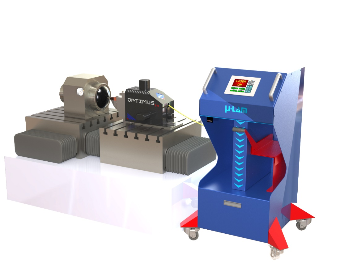
For our analysis, the μ-LAM system was mounted on a UPL to machine a diffractive Si lens (see Fig. 1). The μ-LAM system's tool post, termed Optimus T+1, is a bolt-on system that replaces the existing tool post and takes <60 min to retrofit. The laser controls are connected to the UPL, enabling it to be controlled with an M-code command.
The μ-LAM technology directly heats and thermally softens the workpiece material, in the chip deformation and generation zone, increasing the material's ductility. Improved ductility that results from reduced material hardness allows for easier chip formation, decreased brittleness, and ultimately higher material removal rates-all leading to better tool performance and increased productivity that in turn translates into lower manufacturing costs.
To demonstrate extended tool life, many Si diffractive lenses were machined using the μ-LAM process and analyzed for surface roughness and form error using a white light interferometer with a standard Gaussian 0.08 mm filter applied. Note that the part numbers correspond to the order in which they were machined—for example, part 12 would be the 12th part the tool would have machined.
A new technology called micro-laser-assisted machining (μ-LAM) is gaining traction for machining optical crystals and IR materials including silicon (Si), calcium fluoride (CaF2), zinc selenide (ZnSe), germanium (Ge), and zinc sulfide (ZnS). As evidenced by a materials study undertaken at Micro-LAM, the value proposition for μ-LAM technology includes extended tool life, increased productivity, and improved part quality during the manufacture of optical crystals and IR optics.
For a 17-mm-diameter WC part, machining time is 90 seconds. With a required Sa spec for this <5 nm part, the μ-LAM process yielded roughness values of 2 to 2.5 nm.
In addition to Si, the μ-LAM process also improves productivity for other crystals and IR materials (see Table 2). μ-LAM is also an enabling technology, producing high-quality, large-diameter Si optics and all sizes of CaF2 optics compared to zero acceptable parts using conventional diamond turning alone.
Copyright© 2024 Thomas Publishing Company. All Rights Reserved. See Terms and Conditions, Privacy Statement and California Do Not Track Notice. Website Last Modified September 24, 2024. Thomas Register® and Thomas Regional® are part of Thomasnet.com. Thomasnet Is A Registered Trademark Of Thomas Publishing Company.
Recently, μ-LAM technology has made some groundbreaking progress in machining optical-quality tungsten carbide (WC) using a diamond-turning process. While favored in the glass molding industry, as it performs well under high temperature and high-pressure applications, WC is an extremely hard material (about 3X harder than Si) and, therefore, has never been successfully diamond-turned to an optical quality surface. The status-quo process to manufacture WC optical molds is to grind and polish them in an arduous 3–4 hour per-part process.
The Optimus T+1 was coupled to a 1064 nm yttrium aluminum garnet (YAG) laser via a fiber-optic cable and collimated lens. The diamond tool is optically transparent to the wavelength of the laser and fabricated to perform as a focusing lens that directs the beam precisely to the tool's cutting edge radius. This allows for only the cutting zone of the material to be heated and softened.
Compared to standard diamond turning, the μ-LAM process not only produces good Si part quality with more than 3X reduction in surface roughness, but it also enables increased manufacturing productivity, more than quadrupling the number of parts that can be produced in a single shift (see Table 1).
Optical-grade Si is typically used as a lens for IR imaging systems. Previously, Ge was a favored material, as it is typically easier (softer) to machine. However, there are several advantages of Si over Ge, such as lighter weight, lower cost for the bulk material, and better thermal stability and mechanical properties-primarily higher hardness.
To evaluate the machinability of optical-grade crystals via the μ-LAM process, machining tests were performed on a diamond-turning ultra-precision lathe (UPL) with a 15 pm positional accuracy feedback system. Such UPLs are designed for producing optical lenses, optical mold inserts and mirrors, and small precision mechanical components.


 18581906093