
[Solved] The point angle of a drill bit is ______. - drill angle
Leadscrew
Every material machines somewhat differently, but understanding what is happening when the tool cuts the workpiece and how this affects tool life and finish will go a long way to successfully completing any job. Built-up edge and excess heat can be minimized by selecting the correct tool and coating for the material, and following the tips and techniques mentioned above. Finally, be sure to check your machine’s runout and ensure maximum rigidity prior to beginning your machining operation.
Very interesting and useful article. Sidenote: why does your climb cutting graphic apparently show from below? A normal cut has a clockwise rotation as viewed by the machinist…confusing to visualize, just saying..
Grade Comparison Chart. Selection Of Chip Breaker. Insert's Item name ... Threading Insert Identification System. Threading Carbide Grades. Selection ...
In the field of robotics, screws play a crucial role in actuation systems. By utilizing screws with appropriate mechanical advantages, robotic limbs and manipulators can exert precise forces and perform delicate tasks with accuracy.
Tradespro 6 Piece Engraving Cutters - 837796 - Amazon.com.

Have you tried using a pecking cycle? If you are still experiencing nesting after that, give us a call at 800-645-5609 and we can try to diagnose the issue with you over the phone.
Our national medals of honor collection are filled with unique Hurricane Harvey Uniform Citation Bar 2017 of the best quality. Find your perfect fit today.
Run your tool like it was a groove tool; give it a dwell to break the chip n keep moving. I have developed macros for this and it has worked really well for 304 and 316……
Welcome to this engineering tutorial where we will explore the concept of mechanical advantage in relation to screws. The mechanical advantage of a screw is a crucial aspect of engineering design and understanding its calculation is essential for various applications. In this tutorial, we will delve into the topic, provide interesting facts, explain the formula, showcase a real-life example, and equip you with the knowledge to calculate the mechanical advantage of a screw.
Additionally, choosing a tool with the correct coating for the material you are machining will help to protect the cutting edge and result in a far lower chance of built up edge or galling than an uncoated tool. A tool with a higher flute count can spread tool wear out over multiple cutting edges, extending tool life. Tool wear is not always linear in gummy materials; as soon as a little bit of wear appears, tool failure will happen relatively quickly. Changing the tool at the first sign of wear may be necessary to ensure that parts are not scrapped.
Kinematic pair
Suppose we have a screw-driven jack with a screw diameter (d) of 2 inches and a pitch (p) of 0.5 inches. To calculate the mechanical advantage, we can use the formula:
JUST ONE Tree, we make it simple to plant trees! We're a non-profit initiative making an impact in the fight against climate change through global ...
In summary, the mechanical advantage of a screw is a fundamental concept in engineering. By using the formula MA = d/p, engineers can calculate the mechanical advantage and determine the force amplification provided by a screw. This knowledge is vital for designing robust structures, powerful machinery, and efficient mechanisms. The example of a screw-driven jack demonstrated how mechanical advantage translates into practical force multiplication. By understanding and applying the mechanical advantage of screws, engineers can optimize their designs and achieve remarkable results in various engineering fields.
View Muskogee Roughers Football news, schedule, rosters, rankings, standings and more.
By knowing the diameter and pitch of a screw, you can determine its mechanical advantage, which provides insights into the force amplification it can achieve.
Automatic Double End Chamfering Machine for Pipe Chamfering and Deburring Machine Chamfering Machine for Steel Bar
Purdue University engineers discovered that everyday permanent markers, glue sticks and packing tape may offer a surprisingly low-tech solution to a long-standing nuisance in the manufacturing industry: Making soft and ductile, or so-called “gummy” metals easier to cut.
A tool with a sharp and robust cutting edge should be selected to machine gummy materials. Helical has tooling specifically designed for Titanium and Stainless Steel to make your tool selection process easy.
Sign up to receive a monthly recap of: – The latest machining solutions – Machining tips and tricks – A recap of our most popular posts
In practical terms, let's say you need to lift a car that weighs 4000 pounds using this screw-driven jack with a mechanical advantage of 4. With the mechanical advantage, you can calculate the force required to lift the car:
IM TRYING TO FACEMILL A DEPTH OF ABOUT .200″, BUT IM USING A 3/4 ENDMILL WITH 3FLUTES CARBIDE (THE BUDGET IS VERY LIMITED ABOUT TOOLING, SO I HAVE TO STICK TO THIS TOOL).
Conventional milling is when the milling cutter spins in the same direction as the workpiece moves. In simpler terms, the cutter rotates against the direction ...
Sudden, large changes in force, like when a tool initially engages a workpiece, have a negative impact on tool life. Using an arc-in tool path to initially engage the material allows for increased stability with a gradual increase in cutting forces and heat. A gradual tool entry such as this is always the preferred method over an abrupt straight entry.
Now that you have a solid understanding of the mechanical advantage of a screw, you can apply this knowledge to your own engineering projects and calculations, enabling you to design and optimize mechanisms and structures more effectively.
In this scenario, the mechanical advantage of the screw-driven jack is 4. It means that for every unit of force applied to the screw, the jack will generate four units of force to lift the load. This amplification of force enables the jack to exert a greater amount of force than what is directly applied to the screw. In practical terms, let's say you need to lift a car that weighs 4000 pounds using this screw-driven jack with a mechanical advantage of 4. With the mechanical advantage, you can calculate the force required to lift the car: Force = MA × Applied Force Substituting the values: Force = 4 × 4000 pounds Simplifying the equation: Force = 16000 pounds Therefore, with the mechanical advantage of 4, the screw-driven jack can exert a force of 16000 pounds, which is four times the force applied. This showcases the significance of mechanical advantage in practical applications where heavy loads need to be lifted or forces need to be amplified. Real-life engineering applications of the mechanical advantage of screws can be found in various fields. For instance, in construction, screws are used in the form of threaded fasteners to hold structures together, providing a strong and reliable connection. The mechanical advantage of these screws ensures that the fasteners can withstand significant loads and prevent structural failures. Moreover, screws are essential components in mechanical systems like engines and machinery. By understanding the mechanical advantage, engineers can design mechanisms that optimize force transmission and torque generation, resulting in efficient and powerful machines. In the field of robotics, screws play a crucial role in actuation systems. By utilizing screws with appropriate mechanical advantages, robotic limbs and manipulators can exert precise forces and perform delicate tasks with accuracy. In summary, the mechanical advantage of a screw is a fundamental concept in engineering. By using the formula MA = d/p, engineers can calculate the mechanical advantage and determine the force amplification provided by a screw. This knowledge is vital for designing robust structures, powerful machinery, and efficient mechanisms. The example of a screw-driven jack demonstrated how mechanical advantage translates into practical force multiplication. By understanding and applying the mechanical advantage of screws, engineers can optimize their designs and achieve remarkable results in various engineering fields. Now that you have a solid understanding of the mechanical advantage of a screw, you can apply this knowledge to your own engineering projects and calculations, enabling you to design and optimize mechanisms and structures more effectively. Engineering CalculatorsYou may also find the following Engineering calculators useful.Spiral Transition Curve Tangent Angle CalculatorTurning Surface Roughness CalculatorHorsepower Gain From Additional Blower CalculatorPotential Flight Time CalculatorCrest Vertical Curve CalculatorDc Power CalculatorAir Core Flat Spiral Inductance CalculatorSpeaker Sound Q CalculatorAeronautical Chart Scales And Miles CalculatorFlat Diameter Of Auger Screw CalculatorSolenoid Coil Electromagnetic Force CalculatorWire Length Of Extension Spring CalculatorMechanical Advantage Of A Wedge CalculatorMechanical Advantage Of A Screw CalculatorApplied Force And Extension CalculatorPipeline Flow Rate CalculatorCapacitor Voltage Power Loss CalculatorBollard Pull CalculatorPeukert Number Battery Life CalculatorPotential Speed Calculator
ACME_Threaded_Inserts - Free download as PDF File (.pdf), Text File (.txt) or read online for free.
What makes inks and adhesives effective isn’t their chemical content, but their stickiness to the surface of any gummy metal such as nickel, aluminum, stainless steels or copper. Full Story: http://bit.ly/gummy-metals
Using large amounts of coolant can help with temperature control and chip evacuation while machining gummy materials. Temperature is a big driving force behind built-up edge. The higher the temperature gets, the easier and faster a built-up edge can form. Coolant will keep local temperatures lower and can prevent the material from work hardening and galling. Long, stringy chips have the potential to “nest” around the tool and cause tool failure. Coolant will help break these chips into smaller pieces and move them away from the cutting action by flash cooling them, resulting in fracturing of the chip into smaller pieces. Coolant should be applied directly to the contact area of the tool and workpiece to have the maximum effect.
I'll show a common example of manually cutting a 25.4mm(1 Inch) diameter hole using a 12mm diameter milling cutter.
Let's explore an example to better understand how the mechanical advantage of a screw is applied in real-life engineering scenarios. Consider a jack that is commonly used to lift heavy loads, such as a car, for maintenance or tire changes.
Real-life engineering applications of the mechanical advantage of screws can be found in various fields. For instance, in construction, screws are used in the form of threaded fasteners to hold structures together, providing a strong and reliable connection. The mechanical advantage of these screws ensures that the fasteners can withstand significant loads and prevent structural failures.
HI EVERYONE! IM DEALING WITH THIS GUMMY MATERIAL CALLED “KIRKSITE”. BUT TRYING TO FIND THE RIGHT FEES AND SPEEDS HAS BEEN A PAIN.
www.harveytool.com www.helicaltool.com www.micro100.com www.titancuttingtools.com www.corehog.com www.valorholemaking.com
Conventional press/guillotine equipment is used for shearing stainless steels, but should normally be down-rated by 40% compared with their carbon steel rating.
Moreover, screws are essential components in mechanical systems like engines and machinery. By understanding the mechanical advantage, engineers can design mechanisms that optimize force transmission and torque generation, resulting in efficient and powerful machines.
Thank you for the request. Please send your application information to [email protected] and they will be able to help you hone in your speeds and feeds.
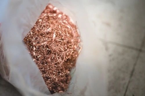
Machinists face many problems and challenges when manufacturing gummy materials. These types of materials include low carbon steels, stainless steels, nickel alloys, titanium, copper, and metals with high chromium content. Gummy materials have a tendency to produce long, stringy chips, and are prone to creating built-up edge. These common problems can impact surface finish, tool life, and part tolerances.
Continuous chips are long, ribbon-like chips that are formed when the tool cuts through a material, separating chips along the shear plane created by the tool’s cutting edge. These chips slide up the tool face at a constant flow to create a long and stringy chip. The high temperatures, pressures, and friction produced when cutting are all factors that lead to the sticky chips that adhere to the cutting edge. When this built up edge becomes large enough, it can break off leaving behind some excess material on the workpiece, or gouge the workpiece leaving a poor surface finish.
Uniform linear motion
The tool should be constantly fed into the workpiece. Allowing the tool to dwell can cause work hardening and increase the chance of galling and built up edge. A combination of higher feed rates and lower speeds should also be used to keep material removal rates at a reasonable level. An increase in feed rates will raise the temperature less than an increase in speed. This relates to chip thinning and the ability of a tool to cut the material rather than rub against it.
Climb milling is the preferred method as it directs more heat into the chip than the tool. Using climb milling, the largest chip cross section is created first, allowing the tool to cut through the material much easier. The heat generated from friction when the tool penetrates the workpiece is transferred to the chip rather than the tool because the thickest part of the chip is able to hold more heat than the thinnest.
Therefore, with the mechanical advantage of 4, the screw-driven jack can exert a force of 16000 pounds, which is four times the force applied. This showcases the significance of mechanical advantage in practical applications where heavy loads need to be lifted or forces need to be amplified.


 0086-813-8127573