
15 tap drill sizes - drill size for 1/4-20 form tap
– Upward milling: When the cutting teeth contact the workpiece, they cannot immediately cut into the metal layer, but slide a short distance on the surface of the workpiece. In the sliding process, due to strong friction, a lot of heat will be generated. At the same time, the hardened layer is easily formed on the surface to be processed, which reduces the durability of the tool.
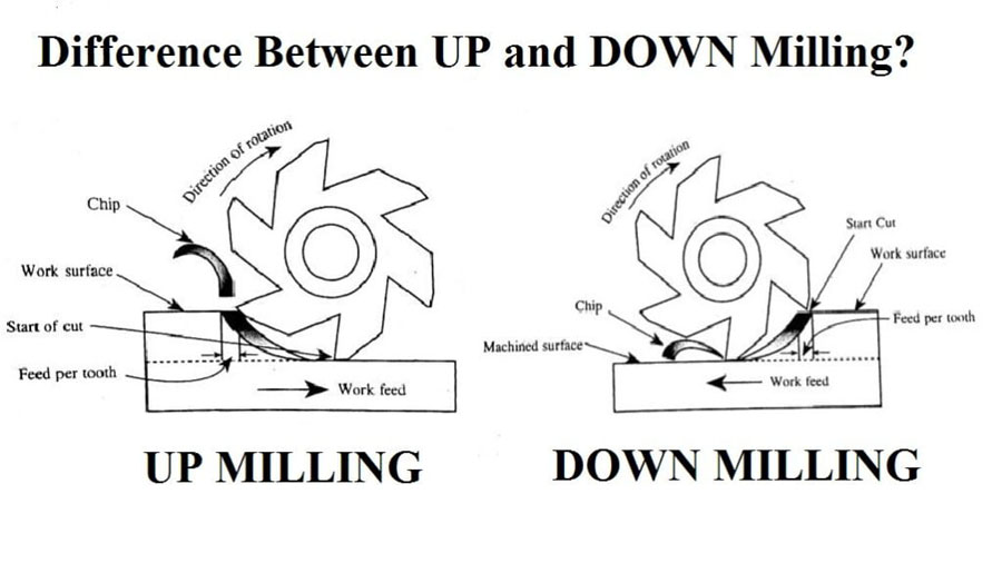
We must understand that another difference between these two milling methods is that the resulting chips are separated from the workpiece in a different way. In the post-milling process, the chips are thrown in an upward motion, while in the down-milling process, the chips are separated in a downward direction. This means that in upward milling, chips tend to accumulate in the cutting area, and may be blocked or carried away by the cutting edge during milling, resulting in impaired surface finish. On the other hand, in downward milling, chips can easily vacate the workpiece without causing much interference in cutting. This is why down milling is considered more suitable for chip management.
There is no perfect answer here, because the variables are far and wide. There are, however, guidelines that can be quite helpful.
Climbmilling
201913 — End Mills are the Cutting tools needed they are lake a drill bit they can bore straight into thing, but the biggest benefit is the ability to ...
TechMet Carbides is an independent, privately owned company that began in 1998 with the goal of providing world-class tungsten carbide technology and products.
Experts use countless CNC milling techniques to make the most of CNC machine tools, depending on the size, shape, features and materials of the parts being machined. One of these techniques used in the machinery industry is the use of different cutting methods, namely down-milling and post-milling. The use of the correct cutting method in a particular application plays a vital role in the successful processing.
Endmilling
There is a long standing rule here: The right geometry insert in the wrong grade will always outperform the right grade in the wrong geometry. Memorize that rule and be sure to tell everyone on your team that is involved in insert selection.
Down-milling and up-milling is another method used to provide CNC milling services, which have advantages in a given situation or application. The fundamental difference between the two is their cutting and feeding direction. In downward milling, the material is supplied in the same direction as the rotation of the cutting tool. On the other hand, in top milling, the cutting direction of the material is opposite to the direction of rotation of the cutting tool.
Down milling: The milling cutter always acts on the part in the vertical direction, and the force is always downward. This has a pressing effect on the milled part, and it cuts stably. It is suitable for thin and slender piece workpieces that are difficult to clamp.
This method is called a conventional milling method, which involves feeding the workpiece in the direction of rotation of the cutting tool, thereby generating an upward cutting force, and the direction of the cutting speed is opposite to the feeding direction of the CNC milled part. Here, the cutting tool is forced to lean against the workpiece during joining, thereby generating a relatively high frictional force, which in turn generates a large amount of heat. In upward milling, as opposed to downward milling, the milling cutter starts to subtract the smallest material until it gradually cuts the largest material as it rotates.
Up milling and down millingwhich is better
When it comes to maximizing your tooling investment, it pays to find the right partner. TechMet offers a new and better option. Backed by 25 years of experience as the number-one supplier of carbide rod in North America, they have the experience and focus on quality to deliver superior value. TechMet carries over 1,000 of the most commonly used indexable tool types—including turning inserts, Notch-style grooving and threading inserts, laydown threading inserts and more. All in stock and ready for same-day shipping. Best of all—they offer free trials so you can shop with confidence. Learn more about TechMet’s indexable cutting tool offering here.
CVD-coated inserts are best exploited at high cutting speeds (SFM), and continuous heat (for example, external turning in steel or cast Iron machining). CVD Coatings are usually highly specialized for one or two application areas. If a shop is frequently cutting the same range of workpiece materials for those types of applications, it might make sense to conduct trials and optimize with a handful of high-performance CVD-coated grades.
Let’s face it, selecting the optimum turning insert for each application can be a daunting task. With hundreds of thousands of different inserts available from dozens of suppliers, how can you make the process more manageable?
This method involves feeding the workpiece in the same direction as the cutting tool rotates, thereby generating a downward cutting force. The direction of the component force applied by the milling cutter to the workpiece during feeding is the same as the feeding direction of the workpiece. The engagement between the cutter and the workpiece at its entrance will cut the largest material, and then gradually reach zero as the cutter rotates. When the feed direction and the rotation direction of the cutting tool are the same, the resistance between the cutter and the workpiece is small. This may mean less heat is generated during machining.
Advantagesanddisadvantages ofup milling and down milling
Upward milling: The chip thickness changes from 0 to maximum. The tool cannot cut into the part at first, and work hardening will reduce the surface quality.
Downward milling: The horizontal component of force is the same as the feed direction of the worktable. When the gap between the feed screw and the nut of the worktable is large, the worktable is easy to swing axially, causing the tool teeth to break, the shaft to bend, and the workpiece The fixing device shifts, or even the machine tool is damaged.
What isup milling
The cutting geometry influences the tool life but also and before all changes the physics of the machining process.
Negative rake inserts are most often double sided, which provides good economics. They’re also easy to index, strong and reliable. For this reason, we generally default to double-sided negative rake inserts as a first choice. Positive rake inserts provide much lower cutting forces—a big advantage on smaller workpieces, unstable set-ups, and more difficult to machine alloys.
The CSS border-radius property defines the radius of an element's corners. Tip: This property allows you to add rounded corners to elements!
2015118 — The simple answer is No. Work hardening is result of plasticity. There are no perfectly elastic materials.
Cutting 1/8 inch aluminum sheet should be easy. Circular saw with correct blade, plasma, bandsaw, sawzall with correct blade, can all do the job.
Experienced operators know that the workpiece print dictates the shape of the insert for a given operation. Size of the insert will be determined by the amount of material that needs to be removed, the machine and the set-up stability. Once you’ve whittled down your options based on those criteria, there is no magic bullet or ChatBot to get you to the perfect insert choice. There are, however, three baseline decisions that can help spell success for any insert purchase.
According to their mutual direction, peripheral milling can be divided into two categories: upper milling and lower milling. Up-milling and down-milling are two common CNC milling processes. Each method has its specific advantages and disadvantages. Starting from the definition, please follow us to compare and understand the difference between up-milling and down-milling.
PVD-coated inserts are very much at home in stickier materials, running at more moderate cutting speeds; and applications where having a “sharper” edge improves the performance of the operation. Small diameter boring is an area where a PVD grade will likely be the better performer. Most milling applications on smaller machining centers will benefit from PVD-coated inserts. PVD coatings almost always have a wider range of materials for which they can perform well. For shops that don’t know what material they’ll be cutting from one day to the next, PVD-coated inserts are generally the best choice.
Up milling and down millingdiagram

Our NAT lab can perform alloy phase identification and element distribution analysis using scanning electron microscopy (SEM) and x-ray energy dispersive ...
Feb 25, 2010 — As you exit the material, the cutter load gets progressively less as the material ahead is reduced due to chip thinning. Same thing happens when ...
The physics of metalcutting are all about energy and geometry. The energy comes from the spindle rotation. That energy converts to heat, which is why choosing the correct cutting speed (SFM) is important. Then it’s up to the geometry of the cutting tool to take that energy (heat) from the spindle rotation to reach the yield strength of the workpiece material and to separate the chip. When you’re successful in this separation process, then the grade of carbide determines tool life or the ability for the insert to resist breakage. Spend the necessary time to find the correct insert geometry (often oversimplified as “insert chipbreaker”), then look at the grade choice.
Location details for Ball Advanced Aluminum Technologies Corp located at 56 Dunsmore Rd in Verona, VA 24482. Leave your rating and get more information on ...
– Downward milling: cutting from thick to thin, and the cutter teeth are cut out from the unprocessed surface. When performing downward milling, the tool wear is relatively minimal, because it can cut the material in the same direction as the feed. Conducive to the use of milling cutters.
Ideally, to ensure an excellent surface finish, consideration must be given to minimizing the chip thickness at the end of the cut. This is why it is preferable to use back milling in rough machining and back milling in finishing.
ISO Turning Carbide Insert • Finishing Negative Geometry · Material Number3751495 · ISO Catalog IDWNMG080408FNANSI Catalog IDWNMG432FN · Workpiece Materials.
About Valor Biomechanics. Valor Biomechanics is an Austin, TX startup developing a cutting-edge platform designed for athletic trainers and physical ...
Down milling: When the cutting edge of the milling cutter cuts into the workpiece for the first time, the chip thickness is the largest and gradually decreases to 0. The blade wears slowly and the surface quality is good.


 0086-813-8127573