
22620 Train Route and Schedule - TEN BSP SF EXP - 22620
The tool’s depth of cuts and the rate at which it is cutting can be used to calculate how many cubic inches per minute (in3/min) are being removed from a workpiece. This equation is extremely useful for comparing cutting tools and examining how cycle times can be improved. Decreased cycle times leads to higher productivity within a shop, which is what all machinists aim for during production.
Best milldecks
I own a Mockmill 100 that I use daily or more. This thing is a work horse and the grind is extemely fine, especially after I double mill grains. I also use it to make rice flour, flax meal, grind random spices etc. If you are a tinkerer, it is really easy to open up to inspect/play with the inner workings (they made it this way deliberately, you don't even need tools to do so). I think it also has the best price of all the home mills.
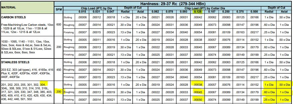
The following table calculates the speeds and feeds for this tool (#50308) and material (304 Stainless) for each operation, based on the chart above:
Thanks for breaking down the basics of speeds and feeds in a way that’s easy to understand! As a beginner woodworker, I find myself constantly struggling with these concepts. Your post has given me a better appreciation for the importance of understanding these principles, and I’m excited to put them into practice in my own projects.
Bestself-mill cards MTG
As shown above, the cutter speed (RPM) is defined by the SFM (based on material) and the cutter diameter. With miniature tooling and/or certain materials the speed calculation sometimes yields an unrealistic spindle speed. For example, a .047” cutter in 6061 aluminum (SFM 1,000) would return a speed of ~81,000 RPM. Since this speed is only attainable with high speed air spindles, the full SFM of 1,000 may not be achievable. In a case like this, it is recommended that the tool is run at the machine’s max speed (that the machinist is comfortable with) and that the appropriate chip load for the diameter is maintained. This produces optimal parameters based on the machine’s top speed. All machines are unique and provide different max speed, therefore these calculations will vary from machine to machine.
It is a constant, maybe not industry, but it is a constant because it is a math conversion and is always the same. Therefore it IS a constant and it is used mostly in the manufacturing and machining industry. So in conclusion, yes, it is an industry used constant
Best millDimir deck
If by greatest volume , you mean not how fast will it grind, but how long, then the best bet is a Retsel Mill Master - while their customer service is rated very poorly here, there is no real argument that it is a beast - a 1 /2 hp with an extremely over engineered gear reduction system, it should last forever. Other machines that will last nearly as long, though turn the stones at a higher speed, include the All Grain allgrainmills, marathon, magic mill - which i think are only available used, As a result of COVID, supplies of the new mills have been spotty, and the price of the used mills have skyrocketed - a check just now on ebay showed listings between $250 and $300 for mills that probably would have sold for around $125 to $150 pre covid.
on the initial feeds and speeds formulas the 3.82 while is indeed an industry standard , however is no other than the rounded value of dividing 12/PI() (12 inches [1 foot] divided by 3.14159….).
SFM is based on the various properties of the given material. Speed, referred to as Rotations Per Minute (RPM) is based off of the SFM and the cutting tool’s diameter. As SFM is tied to the properties of a material, it does not change based upon the operation being performed and remains constant despite changes in chip load calculation. The SFM calculation utilizes the industry standard of 3.82. Here, the cutter diameter of the chosen tool is multiplied by the speed or RPM. This figure is then divided by 3.82 to generate the SFM or Surface Feet per Minute.
Before using a cutting tool, it is necessary to understand tool cutting speeds and feed rates, more often referred to as “speeds and feeds.” Speeds and feeds are the cutting variables used in every milling operation and vary for each tool based on cutter diameter, operation, material, etc. Understanding the right speeds and feeds for your tool and operation before you start machining is critical. These are to be used to set baselines for a particular tool, ensuring proper performance without compromising part finish and tool life.
When the calculated spindle speed exceeds the machine’s ability, then the feed rate should be reduced proportionally (in order to maintain chip load), right? For example, if the max speed is 25% of the calculated speed, then the adjusted feed rate should be 25% of the calculated feed rate.
Adjusting depths of cut can decrease time in cut and overall production time, freeing up machines for additional manufacturing. An example of depth of cut adjustment is seen in High Efficiency Milling, where RDOC is decreased and ADOC is increased. In this method, MRR is increased while also reducing tool wear, leading to higher productivity and more parts per tool.
If you want the finest, it is hard to beat the Lee Household Flour mill - new versions are sold as Royal Lee lee-household-flour-mill/ used ones of the original model Lee show up from time to time on ebay - they don't use a rotating stone to adjust the fineness of the grind, so they can be set to grind very fine, though the downside is that they are slower than most.
Bestblackmillcards MTG
The problem with faster output of a stone mill, that means either the stone must be bigger than the competitors or the stone must spin faster, which will normally mean the flour will come out hotter, and many believe that negatively impacts the nutritional value of the flour. For ex. the Diamant has 5 1/4" burrs diamant-grain-mill other mills use stones that are 3 or 4 inches in diameter.
I totally agree. 3.82 is not an “industry constant”. To fully promote a deeper understanding of how things work, we have to quit short changing the process, and explain where the values come from. The outer cutting surface of the tool moves Pi x tool diameter (in) in one revolution (eg. the equation of the circumference of a circle). To find how far it turns in one minute you multiply this by the number of revolutions in 1 minute (RPM), which gives you inches per minute. To convert that to feet per minute, you must divide by 12 inches in 1 foot. This gives you Tool Dia (in) x Pi (3.14159) x RPM/12. Taking the 12 and dividing by Pi gives you the 3.82, and the equation reduces to SFM=Tool Dia (in) x RPM/3.82.
Sign up to receive a monthly recap of: – The latest machining solutions – Machining tips and tricks – A recap of our most popular posts
The following links have the most up to date information on running parameters for Harvey Tool, Helical, Titan USA, and CoreHog CNC products.
Many tooling manufacturers provide useful speeds and feeds charts calculated specifically for their products. For example, Harvey Tool provides the following chart for a 1/8” diameter end mill, tool #50308. A customer can find the SFM for the material on the left, in this case 304 stainless steel (highlighted in yellow). The chip load (per tooth) can be found by intersecting the tool diameter on the top (blue heading) with the material and operations (based on axial and radial depth of cut), highlighted in the image below.
I like that you mention how the right high-speed air spindles are needed to get the ones that match the calculations. When choosing the components, it would probably be a good idea to ensure you choose the right supplier. This could help you get custom machine spindles and other components that fit your equipment correctly to match the speeds or other aspects that you want.
You’re missing the point entirely. Of course the value is constant, but it shouldn’t be treated as a magic number (aka “industry standard”). Instead, the source of the rounded value should be explained, so people don’t have to try and remember yet another obscure number (it’s not like it helps you do the math in your head either if you round it). It’s 12 divided by PI.
While speeds and feeds are common terms used in the programming of the cutter, the ideal running parameters are also influenced by a myriad of other variables. As speeds and feeds must be well-matched to be effective, the speed of the cutter is used in the calculation of the cutter’s feed rate, measured in Inches Per Minute (IPM). The other part of the equation is the chip load, or material being removed per revolution. It is important to note that chip load per tooth and chip load per tool are different:
It is first necessary to define each of these factors. Cutting speed, also referred to as surface speed, is the difference in speed between the tool and the workpiece, expressed in units of distance over time known as SFM (surface feet per minute). For set-ups with stationary workpieces, SFM is the speed at which a tool moves across the part in the cut. The speed difference must be calculated in set ups where the part and tool are both moving in multi-axis machining set-ups.
These calculations are useful guidelines for running a cutting tool optimally in various applications and materials. However, the tool manufacturer’s recommended parameters are the best place to start for initial numbers and to set a baseline for the best tool performance. After that, it is up to the machinist’s eyes, ears, and experience to help determine the best running parameters, which will vary by set-up, tool, machine, and chosen material. No operation is exactly the same, and nothing occurs in a vacuum. Experience and continued learning will always aid machinists in ensuring the most efficient performance possible in the cut.
Each operation recommends a unique chip load per the depths of cut depending on the operation, thus resulting in different feed rates for the desired application. Since the SFM is based on the material, it will always remain constant for each of the three defined operations.
All original site content copyright 2024 The Fresh Loaf unless stated otherwise. Content posted by community members is their own. The Fresh Loaf is not responsible for community member content. If you see anything inappropriate on the site or have any questions, contact me at floydm at thefreshloaf dot com. This site is powered by Drupal.
Another thing to consider is do you want a very fine grind. Some suggest it is helpful for some products like pasta, others suggest a coarser grind is better for pasta- for bread, there is at least one study that says it is a bell curve, and as you get more fine, at a certain point it decreases openness of the crumb.
On angled tools the cutter diameter changes along the LOC. For example, Helical tool #07001, a flat-ended chamfer cutter with helical flutes, has a tip diameter of .060” and a major/shank diameter of .250”. In a scenario where it was being used to create a 60° edge break, the actual cutting action would happen somewhere between the tip and major/shank diameters. To compensate, the equation below can be used to find the average diameter along the chamfer.
While many of the cutting parameters are set by the tool and workpiece material, the depths of cut taken also affect the feed rate of the tool. The depths of cuts are dictated by the operation being performed – this is often broken down into slotting, roughing, and finishing, though there are many other more specific types of operations.
The next option is a stone or steel burr machine - one stone is fixed , the other rotates and the distance between the two is adjustable to vary how coarse you are grinding. Many here like the Komo, though the Mockmill is a similar design and has its followers. Slower than an impact mill, but usually can get a finer milled flour, though it depends on setting it just right.
An adjustment in internal feed subtracts the differences in cutter diameters from the differences in outer diameters before dividing by the outer dia. difference. On the other hand, adjusting for external feed adds the differences between cutter diameters to the differences in inner diameters before dividing by the inner dia. difference.
Best millcards MTG
Using this calculation, the effective cutter diameter is .155”, which would be used for all Speeds and Feeds calculations.
Hi Scott! Thanks for your feedback and question. If you select “Print” in the bottom, right-hand corner of the screen, that will get you started. Then, change the “Destination” field to “Save as PDF.” Hopefully that works for you – Please let us know if you have any other questions.
Bestbluemillcards MTG
I think there’s a typo in the material type cutting data chart. I believe it should display .125 not .0125 (as used in the example).
These unique operations utilize much different depths of cut, with industry standardized terms as description. Slotting can be described as utilizing 180° of the diameter of the tool engaged in the cut. Roughing on the other hand will typically disperse both ADOC and RDOC relatively evenly. Finally, finishing operations will use substantially more axial depths of cut in relation to radial, leaving the best finish possible on the workpiece.
Best millcards commander
This adjustment is even more important for circular interpolation. Take, for example, a threading application involving a cutter making a circular motion about a pre-drilled hole or boss. For internal adjustment, the feed rate must be lowered to account for the additional engagement. For external adjustment, the feed rate must be increased due to less tool engagement.
Best millplaneswalkers
Feed rates assume a linear motion. However, there are cases in which the path takes an arc, such as in a pocket corner or a circular interpolation. Just as increasing the DOC increases the angle of engagement on a tool, so does taking a nonlinear path. For an internal corner, more of the tool is engaged and, for an external corner, less is engaged. The feed rate must be appropriately compensated for the added or lessened engagement on the tool to provide the most effective and desired IPM for the chosen application.
A chip load that is too large can pack up chips in the cutter, causing poor chip evacuation and eventual breakage. A chip load that is too small can cause rubbing, chatter, tool deflection, and a poor overall cutting action. Finding the correct balance will not only allow for the most efficient cut possible, but also ensures the most efficiency in regard to tool wear. When calculating chip load per tool or IPR, the per tooth chip load is aptly multiplied by the number of flutes on the tool itself.
Material Removal Rate (MRR), while not part of the cutting tool’s program, is a helpful way to calculate a tool’s efficiency. MRR takes into account two very important running parameters: Axial Depth of Cut (ADOC), or the distance a tool engages a workpiece along its centerline, and Radial Depth of Cut (RDOC), or the distance a tool is stepping over into a workpiece. The MRR calculation (seen below) relies on the calculated feed rate. The feed rate (IPM) is multiplied by the radial and axial depths of cut to produce the rate of removal.
I've been using my kitchenaid flour mill for the last 2 years. Does a pretty good job, but looking to upgrade, as the kitchenaid doesn't seem to be keeping up with demand. So, I'm looking for what does the finest grind at the greatest volume. thank you
In the below graphic, Figure A is showcasing a linear path on a part, with a standard engagement. Figure’s B and C demonstrate the increase and decrease of engagement in non-linear, circular toolpaths. Utilizing identical feed rates between the three paths would generate three wildly different IPMs despite similar setups.
www.harveytool.com www.helicaltool.com www.micro100.com www.titancuttingtools.com www.corehog.com www.valorholemaking.com
So that is a pretty open ended question. One option is an impact mill- like the Nutrimill - they are very fast, though not necessarily the finest grind.
You will probably want the Mockmill 200 or higher (the number indicates the grams of flour per minute it will mill) .If you have specific questions I'd be happy to answer them. If you want to see how well it mills flour, my latest blog post features a bread that is 100% fresh milled wheat.
Great question! Yes, if your machine has a limitation and your calculated spindle speed (RPM) is higher than this limitation, you would need to recalculate the feed rate using the spindle speed (RPM) that works in your machine.
Great post! I found it really interesting to learn about the relationship between cutting speed and feed rate in machining. As a beginner machinist, I’ve been struggling to find the right balance between these factors to achieve the desired results. This post has helped me understand the principles behind it and I can’t wait to try out some of the techniques you’ve mentioned. Thanks for sharing!
Take this example, in which a Harvey Tool threadmill #70094, with a .370” cutter diameter, is machining a 9/16-18 internal thread in 17-4 stainless steel. The calculated speed is 2,064 RPM and the linear feed is 8.3 IPM. The thread diameter of a 9/16 thread is .562”, which is used for the inner and outer diameter in both adjustments. After plugging these values into the equations below, the adjusted internal feed becomes 2.8 IMP, while the external feed becomes 13.8 IPM.


 0086-813-8127573