
57 FR 58340 - 58340
Figure B:depicts a standard turning tool with a lead angle. This angle enables for heavy roughing cuts. Ititalso possible to turn the tool to create a semi-square shoulder.
For general purpose machining, use a recommended feed rate of .005 – .020 inches per revolution for roughing and a .002 – .004 inches per revolution for finishing.
Whatisametallatheused for
It has been my experience to take at least three cuts. One to remove excess material quickly: the rough cut, one cut to establish finish and to allow for tool pressure, and one to finish the cut.
Map of 43515 in Ohio + data on income, age, sex, health, poverty, lat/lng and much.
Figure G:depicts a grooving or under-cutting tool. As shown, it is used to cut grooves into the workpiece. When there are proper clearances, the tool can cut deeply, or cut to the left or right.
Inserts can also be mounted on the corresponding specifications of original tool series. -EG Precision profile turning inserts. The Little Squirrel series.
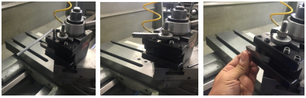
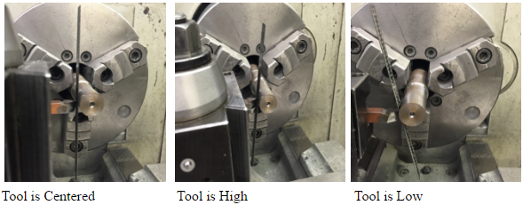
Tailstock Center 1. Reference the center of the tailstock when setting the tool. 2. Position the tip of the tool with the tailstock center. UNIT TEST 1. Please list the ten most important parts of the Lathe. 2. Please list five Lathe safety guidelines. 3. Why is cutting speed important? 4. What is a Toolholder? 5. Where do you mount a Toolholder? 6. How far do you extend the cutting tool in the Toolholder? 7. Please list three different cutting tools. 8. Please describe the positioning of the tool. 9. Explain how to center the workpiece. 10. What are the two way to center the workpiece?
Figure H:depicts a parting tool. Parting tools cut off the stock at a certain length. This tool requires a preformed blade and holder.
4. Feed rate and cutting speed are mostly determined by the material that’s being cut. In addition, the deepness of the cut, size and condition of the lathe, and rigidity of the lathe should still be considered.
Figure F:depicts a facing tool. This cutter is used to face the end of a workpiece to provide for a smooth, flat finish. If the stock has a hole in the center, utilize a half-center to stabilize and support the workpiece.
There are many different tools that can be used for turning, facing, and parting operations on the lathe. Each tool is usually composed of carbide as a base material, but can include other compounds. This section covers the different appearances and uses of lathe cutting tools.
Figure A:depicts a standard turning tool to create a semi-square shoulder. If there is enough material behind the cutting edge, the tool can also be used for roughing.
Have you noticed that when you take a very small cut on the lathe .001 to .002 that the finish is usually poor, and that on the rough cut you made prior to this very light cut, the finish was good? The reason for this is: some tool pressure is desirable when making finish cuts.
5. Roughing cuts (0.01 in. to 0.03 in. depth of cut) for most aluminum alloys run at a feedrate of .005 inches per minute (IPM) to 0.02 IPM while finishing cuts (0.002 in. to 0.012 in. depth of cut) run at 0.002 IPM to 0.004 IPM.
Whatisa lathemachine used for
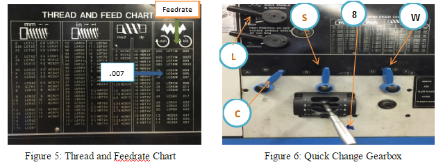
Notice the Feedrate for roughing cuts range from .005 to .020 depending on the material being machined, and .002 to .004 for the finish feed for the different materials.
6. As the softness of the material decreases, the cutting speed increases. Additionally, as the cutting tool material becomes stronger, the cutting speed increases.
We can control the feed on an engine lathe by using the change gears in the quick-change gearbox. Our textbook recommends whenever possible, only two cuts should be taken to bring a diameter to size: a roughing cut and a finishing cut.
Lathemachine operations
Figure D:depicts a rotated standard turning tool. Its nose leads the cutting edge to create light finishing cuts on the outside diameter and face of the shoulder.
Example: Material = Aluminum 3” Cutter, 5 Teeth Chip Load = 0.018 per tooth RPM = 3000 IPS = 0.018 × 5 × 3000 = 270 Inches Per Minute
CNC Spoilboard Surfacing. Download Catalog(PDF) · Home › Straight Router Bits› CNC Bits ›CNC Spoilboard Surfacing ... 1/2'' Shank Straight Bits (60) · Left Hand - ...
Home Depot. Free shipping. New tab icon. Product Image. $7,339.00 ... LY CNC 6020 Metal Aluminum Milling Carving Engraving Machine 400W 3-5 Axis DIY CNC.
Parts oflathemachine
The feed of on lathe, or the distance the carriage will travel in on revolution of the spindle, depends on the speed of the feed rod or lead screw. This is controlled by the change gears in the quick-change gearbox. This quick change gearbox obtains its drive from the head stock spindle through the end gear train. A feeds and thread chart mounted on the front of the quick-change gearbox indicates the various feeds and metric pitches or thread per inch which may be obtained by setting levers to the positions indicated.
Mar 15, 2024 — CNC Machining: Understanding Feeds and Speeds · Cut speed (or surface speed) is the speed at the outside edge of the part as it is rotating. It ...
Whenever possible, only two cut should be taken to bring a diameter cut. Since the purpose of a rough cut is to remove excess material quickly and surface finish is not too important. A coarse feed should be used. The finishing cut is used to bring the diameter to size and produce a good surface finish and therefore a fine feed should be used.
7.W = Select Feed Ranges and change to W on this lever (See Figure 3) Before turning on the lathe, be sure all levers are fully engaged by turning the headstock spindle by hand, and see that the feed rod turns.
To operate any machine efficiently, the machinist must learn the importance of cutting speeds and feeds. A lot of time can be lost if the machines are not set at the proper speed and feeds for the workpiece.
Choose Whitaker Brothers' corner rounding paper cutter machines to achieve perfectly rounded corners with ease. ... rounder for your cutting and trimming needs.
5 uses oflathemachine
If you were cutting thread all day long: day in and day out. You might set the lathe up for only two cuts. One cut to remove all but .002 or .003 of material and the last cut to hold size and finish. This is done all the time in some shops today.
Titanium is often described as difficult to machine. This is somewhat of a misnomer, titanium is only difficult to machine if you are trying to work with it in ...
In order to eliminate this time loss, we can, and should, use recommended metal-removal rates that have been researched and tested by steel and cutting-tool manufactures. We can find these cutting speeds and metal removal rates in our appendix or in the Machinery’s Handbook.
The lathes are designed to operate at various spindle speeds for machining of different materials. There speeds are measured in RPM (revolutions per minute) and are changed by the cone pulleys or gear levels. One a belt-driven lathe, various speeds are obtained by changing the flat belt and the back gear drive. One the geared-head lathe speeds are changed by moving the speed levers into proper positions according to the RPM chart fastened to the lathe machine (mostly on headstock). While shifting the lever positions, place one hand on the faceplate or chuck, and form the face plate slowly by hand. This will enable the levers for engage the gear teeth without clashing. Never change speeds when the lathe is running on lathers equipped with variable speed drivers, the speed is changed by turning a dial of handle while he machine is running.
As always we should be aware of safety requirements and attempt to observe safety rules in order to eliminate serious injury to ourselves or others.
Howdoes a lathework
4. What would the RPM be if we were turning a 1.00” diameter workpiece made out of mild steel, using Carbide cutting tool?
BT Steep taper JIS (MAS 403). Zurück BT Steep taper JIS (MAS 403) · BT30. Zurück BT30 Shrink Fit Chuck Collet Chuck Hydraulic Chuck Face Mill Arbor Blank ...
Manufacturing Processes 4-5 Copyright © by LamNgeun Virasak is licensed under a Creative Commons Attribution 4.0 International License, except where otherwise noted.
The lathe is a very versatile and important machine to know how to operate. This machine rotates a cylindrical object against a tool that the individual controls. The lathe is the forerunner of all machine tools. The work is held and rotated on its axis while the cutting tool is advanced along the line of a desired cut. The lathe is one of the most versatile machine tools used in industry. With suitable attachments, the lather may be used for turning, tapering, form turning, screw cutting, facing, dulling, boring, spinning, grinding, polishing operation. Cutting operations are performed with a cutting tool fed either parallel or at right angles to the axis of the work. The cutting tool may also be fed at an angle, relative to the axis of the work, for machining taper and angles. On a lathe, the tailstock does not rotate. Instead, the spindle that holds the stock rotates. Collets, centers, three jaw chucks, and other work-holding attachments can all be held in spindle. The tailstock can hold tools for drilling, threading, reaming, or cutting tapers. Additionally, it can support the end of the workpiece using a center and can be adjusted to adapt to different workpiece lengths.
A lathe work cutting speed may be defined as the rate at which a point on the work circumference travels past the cutting tool. Cutting speed is always expressed in meters per minute (m/min) or in feet per minute (ft/min.) industry demands that machining operations be performed as quickly as possible; therefore current cutting speeds must be used for the type of material being cut. If a cutting speed is too high, the cutting tool edge breaks down rapidly, resulting in time lost recondition the tool. With too slow a cutting speed, time will be lost for the machining operation, resulting in low production rates. Based on research and testing by steel and cutting tool manufacturers, see lathe cutting speed table below. The cutting speeds for high speed steel listed below are recommended for efficient metal removal rates. These speeds may be varied slightly to shift factors such as the condition of the machine, the type of work material and sand or hard spots in the metal. The RPM at which the lathe should be set for cutting metals is as follows:
16. Make sure that the tailstock is locked in place and that the proper adjustments are made if the work is being turned between centers.
Types oflathemachine
6. When installing and removing chucks, face plates, and centers, always be sure all mating surfaces are clean and free from burrs.
Wood Boring Drill Bit, Steel, carbon steel, Wood, Drill holes with large diameters. Can Drill Bits Go Through Metal? Not all drill bits can go through ...
Uses oflathemachine in workshop
Wear glasses, short sleeves, no tie, no rings, no trying to stop the work by hand. Stop the machine before trying to check the work. Don’t know how it works? –“Don’t run it.” Don’t use rags when the machine is running.
The recommended feeds for cutting various materials when using a high speed steel cutting tools listed in table below. For general purpose machining a .005 – .020 inch feed for roughing and a .012 to .004 inch feed for finishing is recommended.
5. Place the tool post holder to the left of the compound slide. This will ensure that the compound slide will not run into the spindle or chuck attachments.
• Check that the line center is running true. If it is not running true, remove the center, clean all surfaces, and replace the center. Check again for trueness.
When set too high the tool breaks down quickly, time is lost replacing or reconditioning the tool. Too low of a CS results in low production.
Notice the largest roughing cuts range from .010 to .030 depending on the material being machined, and .002 to .012 for the finish feed for the different materials.
Figure C:nose has a very large radius, which helps with fine finishes on both light and heavy cuts. The tool can also be used to form a corner radius.
1. Remove the chuck key from the chuck immediately after use. Do not turn the lathe on if the chuck is still in the chuck key.
2 days ago — Something I've started doing a lot of recently of is creating and exporting my own multiple drum/hit samples that I've made.
To reposition the cutting tool, move the cross slide and lathe saddle by hand. Power feeds are also available. Exact procedures are dependent on the machine. The compound provides a third axis of motion, and its angle can be altered to cut tapers at any angle.
22. Make sure the machine is turned off and clean before leaving the workspace. Always remove the chuck wrench after use, avoid horseplay, keep floor area clean. Use care when cleaning the lathe, the cutting tools are sharp, the chips are sharp, and the workpiece may be sharp.
7. If more accuracy is needed when positioning the saddle, use a dial indicator that is attached to the saddle. Dial indicators press against stops.
• Place the end of the workpiece in the chuck and slide the tailstock up until it supports the other end of the workpiece.
The feed of a lathe is the distance the cutting tool advances along the length of the work for every revolution of the spindle. For example, if the lathe is set for a .020 inch feed, the cutting tool will travel the length of the work .020 inch for every complete turn that work makes. The feed of a lathe is dependent upon the speed of the lead screw or feed rod. The speed is controlled by the change gears in the quick change gearbox.
Manufacturing Processes 4-5 Copyright © by LamNgeun Virasak is licensed under a Creative Commons Attribution 4.0 International License, except where otherwise noted.


 0086-813-8127573