
ABB INS 54210 Color-Keyed® Compression Lug with ... - 54210
Turning insertchart
A standard twist drill has a tip angle of between 115 degrees and 145 [1]. By changing this angle, you can create optimal cutting and chip removal for ...
Carbideinsertidentification chart PDF
Computer numerical control (CNC) machining is one of the world’s most widely used subtractive manufacturing technologies because of its high accuracy and precision. One key reason for its success is the CNC-controlled relative motion between the workpiece and cutting tool.
1/8" Dia, 3/4" LOC, 3/8" Shank Dia, 3 Flute, 28 Degree Helix, Uncoated, Series 23S, Tapered Square End Mill - 32327.
The link that exists between the nose radius and the depth of cut is one factor that might have an effect on the vibrational tendencies. The radial forces that are responsible for driving the insert away from the cutting surface become more axial as the depth of cut increases. These forces are caused by the increase in the depth of cut.
Turninginserts types
When completing, positive inserts are always the ideal option since they generate reduced cutting forces and allow you to cut at lower depths, avoiding vibration. The most common Positive Inserts are CCMT (rhomboid 80 degree), DCMT (diamond 55 degree), VCMT or VBMT (diamond 35 degree).
One way to reduce the effect of chip thinning is to machine your workpiece at high feed rates. Doing this helps to improve your productivity and tool life.
As a rule, the harder the workpiece material, the slower the cutting speed you should implement during machining. For example, materials like titanium will require a lower cutting speed compared to steel.
Insertnose radius chart
Because of this quality, double Negative angle cutter inserts are able to display stronger insert strength when compared to positive/negative cutters and double Positive angle cutter inserts. Positive angle cutter inserts also have this feature. Due to the geometry of double negative angle inserts, there is a possibility of poor chip flow, which might lead to worries about clogging. The geometry of these inserts is like this despite the fact that they are quite robust and durable.
It is essential to have a machine that has the necessary power, in addition to a rigid setup, in order to ensure that the cutting tool and the workpiece are securely attached. Cast iron is an excellent material for using negative angle insert geometries; however, in order to make advantage of these geometries, a stiff setup is required. Also, keep in mind that recent developments in technology have made it possible to include chip breakers inside inserts. This is something that was previously impossible. Because of this, modern negative angle inserts may be machined with a larger degree of flexibility than was previously feasible. This was not the case in the past. Because of this, negative angle inserts are capable of processing a wide variety of materials effectively provided that the appropriate chip groove profile is used.
Insertclearance angle
Negative inserts are the most lasting and dependable solution for roughing and general turning applications because of the sturdy inserts shapes and thickness. This is due to the fact that negative inserts provide larger feed rates and deeper depths of cut than other kinds of inserts. When completing, the use of positive inserts is nearly always the optimum option since, in comparison to other kinds, they give lower cutting pressures. As a result of this, it is feasible to complete the cutting process at shallower depths, which will result in a reduction in vibration. The price of a positive and negative insert is practically the same; however, if you acquire twice as many cutting edges as you did before, the price that you pay for each cutting edge will be cut in half. This is because the price of an insert is determined by the number of cutting edges that are purchased. Get in contact with HUANA if you have any questions or concerns about positive angle inserts and negative angle inserts, or if you are interested in purchasing either kind of insert.
To determine the optimum cutting speed for your machining project, you need to consider the workpiece hardness and the strength of the cutting tool.
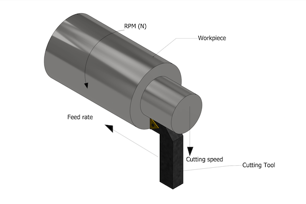
In contrast, we can compare the feed rate to the wheels’ rotation in the car analogy. Feed rate is simply the distance the tool travels during one revolution of the part. We measure it in inch per revolution (inch/rev) or millimeter per revolution (mm/rev).
When performing turning operations, it is essential to take into account the nose radius, sometimes referred to as the RE. Inserts are available for purchase in a variety of nose radius diameters in a wide range of sizes. The selection, which is controlled by the depth of cut and the feed rate, has an effect on the surface finish, chip breaking, and insert strength. Both of these factors are impacted by the selection.
Hardness describes the resistance of a material to deformation induced by abrasion, indentation, or scratching. Harder workpiece materials demand special attention during machining since they can easily reduce the performance life of cutting tools.
Circle Machine 2831774 | CCPI25065R | Indexable Boring Bar | 0.3600 Min Bore Diameter | 0.0100 Cutting Height | 6 Overall Length | 1/4 Shank Diameter.
Insert geometrychart
Apr 9, 2024 — This guide will walk you through the step-by-step process and give the best tips about how to drill into concrete.
Hillman's silver masonry nails are perfect for attaching wood fixtures to interior brick and concrete walls by hand. Whether hanging shelves, installing ...
CNC milling is a CNC process that involves the use of rotating cutters to remove portions of a block of material (or workpiece) till the desired custom shape (or feature) is made. It allows manufacturers to create intricate parts accurately while meeting tight...
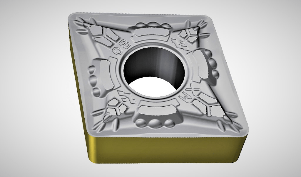
Positive inserts, like the VBMT insert seen in the picture, have a relief angle that isn’t equal to zero. This is because positive inserts are inserted into holes that are already drilled. The insert has cutting edges on the opposite side of the component from which it was cut. The underside of the blade is not appropriate for cutting and serves no use other than to rest on the pocket of the tool holder. The insert depicted in this example is a V with a 35-degree angle, but the same general idea applies to any shape, including D, R, S, T, and so on.
Feed rates also affect the tool life and power consumption during machining, but their effects are usually negligible compared to cutting force. Instead, feed rates are more likely to affect the machining time and surface finish of the machined part.
Cutting speed can be compared to the linear velocity of the car, which depends on the wheels’ diameter and RPM. It measures the linear distance moved by the cutting tool against the machined part at a given time. Cutting speed is measured in millimeters per minute (mm/min), meters per minute (m/min), or feet per minute (ft/min).
Millinginserttypes
Roughing Inserts: Combinations of a high feed rate, and depth of cut for the cut. Operations that need the most cutting-edge level of security.
Dec 7, 2023 — Milling tools can be categorized into various types, including End Mill,Face Milling Cutter,Three-Edge End Mill,Keyway Milling Cutter,Saw ...
Inserts with a negative angle are used to cut through materials with a high strength rating since they are stronger. When inserts with a negative angle are utilized, the cutting edges may gain enhanced strength, which is beneficial.
Medium Inserts: Operations ranging from medium to light roughing. A diverse selection of depth of cut and feed rate combinations are available.
When choosing the form of the insert, consideration should be given to the appropriate level of accessibility for the tool’s entry angle. In order to ensure the insert’s strength and dependability, the nose angle should be increased to its maximum achievable value. Having said that, this aspect needs to be weighed against the several different cuts that have to be carried out. A big nose angle is robust, but it calls for a greater amount of machine power and has a greater propensity to vibrate. A tiny nose angle is weaker and has a smaller cutting edge engagement, both of which might make it more vulnerable to the effects of heat. A large nose angle, on the other hand, has a larger cutting edge engagement.
Negative angle inserts have an orientation that sends the cutting forces farther back from the edge of the insert by using a combination of negative axial and negative radial rake angles. This allows the cutting forces to be directed further away from the edge of the insert. The rake angle is the result of combining these angles together.
CNMGInsert
In the following paragraphs, we will explain how to go about picking the most appropriate insert shape and grade for the particular duties you have. When selecting an insert, there are a lot of different factors to think about. In order to obtain effective chip control and machining performance, it is important to carefully pick the insert geometry, insert grade, insert shape (nose angle), insert size, nose radius, and entry (lead) angle.
The geometry of the insert and its grade are complementary to one another. For instance, the toughness of a grade may make up for a lack of strength in an insert geometry if the insert geometry is designed properly.
The relief angle is represented by the letter that comes after the first letter in the name of an insert (for example, B in VBMT). N signifies 0 degrees, a negative insert. A non-zero angle, often known as a positive insert, is denoted by any other letter (E.g., B is 5 degrees, C is 7, P is 11). (E.g., B is 5 degrees, C is 7, P is 11). If the second letter of the insert’s name is an N, then the number of cutting edges on the insert will often rise by a factor of two. This is because N is the letter that comes second in the insert’s name. If the letter is anything other than an N, then you will only receive cutting edges on one face. As an example, VBMT160408 only has two edges, but VNMG160408 has four edges.
When it comes to selecting the appropriate insert, finding the insert that is most suited to the task at hand is just half the fight. The last step consists of choosing the most appropriate grade and chip breaker.
The two distinct types of inserts have certain similarities in their qualities, which are outlined in the following list:
Choose from our selection of 1/4"-20 taps, including general purpose taps, tap sets, and more. In stock and ready to ship.
Inserts with a positive angle of attack are typically utilized for cutting through softer materials. Less force is needed to cut through it. However, the cutting edge becomes less effective as the positive value of the rake angle increases. The cutting edge of the tool has a greater propensity to be severed when there is force exerted on the tool. Using inserts with a positive angle makes the tool sharper and more pointed, but they also lower the cutting edge’s strength. It contributes to the avoidance of the creation of build-up edge chip in ductile materials and aids in the production of continued chip in ductile materials.
Finishing Inserts: Operations using finishing inserts should be performed at shallow depths of cut and slow feed rates. Operations that need just a little amount of cutting force.
To help you understand these two terms, let’s consider a simple analogy of a car moving at a linear speed of 60 km/hr with wheels rotating at 500 rpm. You’d agree that the wheels’ diameter and rotation are responsible for the car’s movement along a paved road. But when describing the vehicle’s speed to a friend, you’d explain it in terms of kilometers per hour.
The geometries of inserts may be broken down into three fundamental types that are most suited for finishing, medium, and roughing operations respectively.
Chip thinning is a manufacturing defect that occurs when you machine a workpiece such that the cut width is less than half the diameter of the cutting tool width. This reduces the chip load (the size or amount of material removed by the cutting tool per revolution), causing greater lead times.
It is to one’s benefit to have a bigger percentage of axial forces than radial forces. Having more axial forces than radial forces. When there is a large radial force acting on the cutting process, it may have an adverse influence, which may result in vibration and a poor surface quality. This may be the case when there is an excessive amount of radial force acting on the cutting operation. As a general rule of thumb, you should choose a nose radius that is either the exact same size as the depth of cut or a little smaller size than the depth of cut.
201544 — The one I use suggests for a 3mm dia 2 flute cutter with a cut depth of 1.5mm the spindle speed should be 16,000 rpm and feed rate 950mm/min for ...
Gensun Precision Machining offers rapid prototyping and precision machining services for innovative companies around the world. Whether you need a custom prototype, low-volume production, or high-volume production, our service is second to none. With a strong emphasis on quality control, we get the job done right, every time!
Insert with a negative rake angle, which may be utilized either double-sided or single-sided, has a high edge strength, has zero clearance, is the ideal choice for external turning, and is effective for heavy cutting situations.
Companies around the world use CNC machining to craft high-quality components from diverse materials like ceramics, wood, and composites. Metal and plastic take the forefront in mass production, with metals enjoying wider machinability. Machinists can adeptly tackle...
Determine the appropriate size of the insert based on the requirements of the application as well as the available area for the cutting tool in the application. When the insert size is increased, the stability also increases. Insert sizes typically greater than IC 25 millimeters are used for heavy-duty machining (1 inch). After completion, there is often the possibility of shrinking the size.
Both positive and negative angle inserts relate to the angle of the cutting edge in relation to the machined surface. Positive angle inserts have a positive angle, and negative angle inserts have a negative angle. The rake angle of the cutting tool is defined as the angle of orientation of the tool’s rake surface from the reference plane (R), and it is measured on some other plane. It is possible for it to be referred to by a variety of names, some of which depend on the plane on which it is projected and measured. At the same time, the rake angle might have a positive value, a negative value, or perhaps no value at all depending on the angle at which the rake surface is inclined with respect to the reference plane. Each of these three varieties comes with its own unique set of benefits and drawbacks. This value has the potential to affect the cutting force and power consumption during machining, as well as the life of the cutting tool, chip deviation, shear angle, tool life, and other factors. The rake angle has an indirect impact on machinability as well.
The evolution of CNC machining has been marked by significant technological advancements. From the early days of punch tape and rudimentary programming, CNC machining has evolved to incorporate sophisticated software and high-speed, multi-axis machines. In recent...
The clearance angle is where the primary difference between inserts with a positive angle and inserts with a negative angle may be found.
It should come as no surprise that the first letter in the codes for the inserts indicates the form of the insert, whilst the second letter in the code specifies the clearance angle. On the description chart is an insert with the number CCMT120206. The second letter “C” in this letter sequence indicates that the clearance angle is 7 degrees. In this instance, the angle is more than 0 degrees, which is why we refer to it as a positive angle insert. In the same vein, an insert with the coding VNMG160804 reveals that the second letter is a “N.” You can tell that it is a negative angle insert since the explanation chart has the letter “N” next to the clearance angle of 0 degrees. The bottom line is that the presence of the letter “N” in an insert code indicates unequivocally that the insert is made of carbide.
The insert grade is chosen in large part with consideration given to the following criteria: the component material (ISO P, M, K, N, S, or H); the kind of procedure (finishing, medium, roughing) The working conditions of the machine (good, average, difficult)
The helix angle of the twist drill is generally 25° to 32°. In addition, the front end of the drill bit is sharpened to form a cutting portion, and the spiral ...
To begin, inserts with negative angles often have clearance angles of zero degrees. On the other hand, the positive angle inserts will always have a clearance angle that falls somewhere between 0 and 90 degrees.
Stainless steel uses over 65% of all nickel produced. · Nickel-metal hydride and rechargeable nickel-cadmium batteries are two types of batteries that contain ...
On the other hand, any carbide inserts that do not include the letter “N” in the second position are considered to be positive angle inserts. Single-sided cutting, minimal cutting forces, and side clearance are only some of the characteristics that are offered by the positive angle inserts. In addition to this, it is an excellent option for turning relatively thin components internally as well as turning them outside. Negative angle inserts, on the other hand, can be single or double-sided, have zero-clearance, are designed for heavy cutting circumstances, and have great edge strength.
The relief angle of negative inserts, like the VNMG insert depicted in the figure, is equal to zero. This is because negative inserts have a negative thickness. Because of this, the two sides of the insert seem exactly the same, yet both sides include edges that may cut.
Some cutters retain the positive angle inserts in such a manner that it provides a positive rake angle both axially and radially. This allows for highly free cutting as well as clean and silent machining. This configuration not only provides very low cutting force but also achieves a great surface finish, work hardening on the surface is reduced to a minimum, and excellent surface finish. Machining non-ferrous materials, such as aluminum, copper, and non-metallic materials, and even steels on smaller machines with low power ratings is possible using geometries like these. Because they are more delicate (which can result in cutting edge chippage) and have the potential to pull the workpiece off the table, these positive angle inserts require a special amount of care during the setting up process.
Make use of wiper inserts to provide either a better surface finish while retaining conventional cutting data or a maintained surface finish while drastically increasing feed rate. The wiper geometry known as WMX is First Choice, and it serves as an excellent place of departure for the vast majority of applications. There is always a fruitful option available, even when the circumstances change. In the event that vibration issues arise, using a wiper shape that is positive will help reduce the amount of force required and keep production levels stable.
But what is cutting speed, and how does it differ from feed rate? And how do these machining parameters contribute to the success of your manufacturing project? This article answers all of these questions and more.
Now that you understand the differences between feed rate vs. cutting speed, you’d agree that these two machining parameters are important during CNC machining. However, even after you choose the ideal cutting speed and feeds, the success of your project also depends on the machine shop you work with.
A positive insert will have a clearance angle that is more than zero degrees, while a negative insert will have a clearance angle that is greater than zero degrees but less than ninety degrees (for example, 7 degrees of clearance). The negative type insert explains how the insert need to be constructed so that it will tilt appropriately when it is put in the holder.
Still considering the car analogy, a wheel rotating at higher RPMs will likely consume more power and wear more quickly than wheels turning at lower RPMs. This wear is due to the friction and high temperatures between the tires and the road. Similarly, cutting speed affects the tool life, cutting temperature, and power consumption.

Clearance angle, single-sided cutting, positive angle insert, low cutting forces, side clearance, and angle of clearance are some of the features that are included.
Negative inserts are the strongest and best solution for roughing and standard turning applications because their solid forms and thickness allow for greater depths of cut and higher feed rates. The most common Negative Inserts are CNMG (rhomboid 80 degree), DNMG (diamond 55 degree), and WNMG (trigon 80 degree). With a 45-degree approach angle that allows for greater depths of cut and lower cutting loads, SNMGs are a good choice for heavy roughing jobs.
Gensun Precision is a leading provider of CNC machining services across Asia. Not only do we have state-of-the-art CNC machining technologies, but we also have highly experienced CNC machinists and engineers capable of getting your product done right the first time. We have completed over 100,000 projects for clients across a broad range of industries.
The strength of the cutting tool plays a role in the allowable cutting speeds for machining operations. For example, you can use high cutting speeds when machining with a cutting tool made of high-strength materials like diamond and carbon boron nitride, whereas tools made of high-speed steel demand lower cutting speeds.


 0086-813-8127573