
Acme 215-066303 SS Keylocking Threaded Inserts 5/16"- ... - acme threaded inserts
Next lookup the recommended feed per revolution for the equivalent size drill bit in Table 2 (fr ≈ 0.006 in/rev) and calculate the feed rate using Equation 3:
First, lookup the recommended surface speed in Table 1 (V ≈ 250 ft/min) and calculate the spindle speed from Equation 2:
6. The bottom shape of blind holes should be that made by a standard drill point, as shown in the image below. When flat-bottom holes are required, allow a standard drill point (118° or 140° with stainless steel).
3. Allow chip clearance with internal threads. Through holes are preferable to blind holes because of more straightforward clearance for tools and chips, especially when secondary operations such as reaming or tapping are required.
8. Avoid designing parts with tiny holes if the small size is unnecessary for your part’s application. This is because small drills are more susceptible to breakage. About 3 mm diameter is a desirable minimum for convenient production.
The exit surface of the drill also should be perpendicular to the axis of the drill to avoid breakage problems as the drill leaves the work, as shown below.
TIP: Plunging should generally be performed at 75% of the speed and 25% of the feedrate of the calculated peripheral cutting parameters.
TIP1: Recommended peck depth when drilling less than 3xD (e.g. 3 drill diameters) with flooded coolant is one drill diameter, or when applying oil manually, or under low pressure, is 50% of drill diameter.
First, lookup the recommended surface speed in Table 1 (V ≈ 100 ft/min) and calculate the spindle speed from Equation 2:
Cuttingspeed chart
To optimize the CNC drilling process, designers must consider various factors such as drill entry and exit surfaces, hole straightness, chip clearance, threaded product design, hole shape, and overall part layout. Each of these aspects contributes to the overall success of CNC drilling and influences the final quality and functionality of the workpiece.
TIP1: Since annular cutting is a plunging operation, it should generally be performed at 75% of the speed and 25% of the feedrate of the calculated peripheral cutting parameters (as with endmill plunging).
Next lookup the recommended feed per revolution for the drill bit in Table 2 (fr ≈ 0.004 in/rev) and calculate the feed rate using Equation 3:
4. Shorten your threads. The first four pitchs take most of the load. You can save that space if you don’t have a defined calculated load. If you don’t know the pitch, everything longer then the diameter is unnecessary.
1. The drill entry surface should be perpendicular to the drill bit to avoid starting problems and help ensure the hole is in the proper location, like in the photo below.
End millRPMChart
Every metal cutting operation requires selection of proper cutting parameters for success. As a DML TA, you need to understand basic calculations that will allow the tools you use to work as intended.
TIP: IF this was being performed on a CNC lathe, typical parting feed rates vary between 0.001 in/rev (for steels) and 0.005 in/rev (for plastics). But remember, do NOT use the power feed when parting on a manual lathe unless you own the machine!
Next, lookup the recommended feed per tooth (chipload) in Table 3 (ft ≈ 0.004 in/tooth) and calculate the feed rate using Equation 3:
Milling speedsandfeedsChartMetric
14. If a blind hole requires reaming, good practice calls for extra drilled depth to provide room for chips. Reamed hole must be design according to the specifications tools manufacturers. The linked table shows you the offset for the reaming.
Next, calculate the feed rate used for plunging. Remember annular cutters should be fed at approximately 25% of the feedrate for an equivalent sized endmill. From Table 3, lookup the recommended feed per tooth for a 1″ HSS endmill (ft ≈ 0.008 in/tooth) and calculate the plunge feed rate using Equation 3:
Example 2B: Calculate the speed and feed for a 1/2″ diameter, 3 flute carbide endmill if peripheral and plunge cutting in aluminum using a CNC milling machine in lab.
Carbideend MillRPMchart
TIP2: When drilling deeper holes (> 3xD) without high pressure TSC (thru spindle coolant), reduce spindle speed an additional 50%.
Note: when applying oil manually, scale the feed and speed back to 60%, so N ≈ 420 rpm and f ≈ 4.8 in/min (final answer). This is close enough to 500 rpm that I would first try this tool at the low end of high range with good oil application and see how it goes.
TIP: Reamers should generally be run at half the spindle speed and twice the feed per revolution of the equivalent sized drill bit.
MakerVerse is your platform for sourcing industrial parts, providing instant access to a vetted supply chain and a full range of manufacturing technologies. With AI-powered quoting, order management, and fulfillment, MakerVerse helps with everything from initial prototypes to full-scale production.
By adhering to these guidelines, you can can ensure smooth operations, avoid potential issues, and achieve desired outcomes in their CNC drilling projects.
5. The design of threaded products should include a chamfer at the ends of the external threads and a countersink at the ends of the internal threads. These inclined surfaces prevent the formation of finlike threads at the ends, help minimize burrs, and assist the threading tool in cutting or forming the threads.
TIP: Countersinking should generally be performed at 25% of the speed and the same feed per revolution as the equivalent sized drill.
First, lookup the recommended surface speeds in Table 1 (VALUM ≈ 625 ft/min, VSTEEL ≈ 250 ft/min (notice the 2.5 multiplier))
TIP: When working with plastics with good machinability, use the cutting parameters for aluminum up until the point that the plastic melts.
The table below contains a recommended surface speeds for common materials when using DML equipment. These values are conservative because our primary goal is fostering a safe learning environment (for our users and our tools!), not trying to squeeze every second out of each operation.
Example 5: Calculate the speeds for parting off 1 diameter aluminum and 1 diameter mild steel workpieces on the lathe using the standard carbide part-off inserts.
2. If the straightness of the finished hole is particularly critical, it is best to avoid interrupted cuts. Some deflection will occur if the drill intersects another opening on one side. Even when straightness is not critical, the center point of the drill must remain in the material throughout the cut to avoid extreme deflection and possible drill breakage.
Milling speedsandfeedschartpdf
A general rule of thumb for materials which are strong enough to support the drilling process is that fr is between 1 - 3% of the drill diameter, depending on the material strength.
7. Avoid deep holes (over 8 times diameter) because of chip-clearance problems and possible deviations from straightness. Especial drills on the market can reach 40 times diameter with price tags around 150-400€; avoid them.
Aluminum millingspeed chart
Next, lookup the recommended feed per tooth (chipload) in Table 3 (ft ≈ 0.008 in/tooth) and calculate the feed rate using Equation 3:
Please begin by reviewing the comprehensive course document on this topic, as it clearly explains the process of calculating these parameters for drilling and milling operations. The governing equations are summarized below.
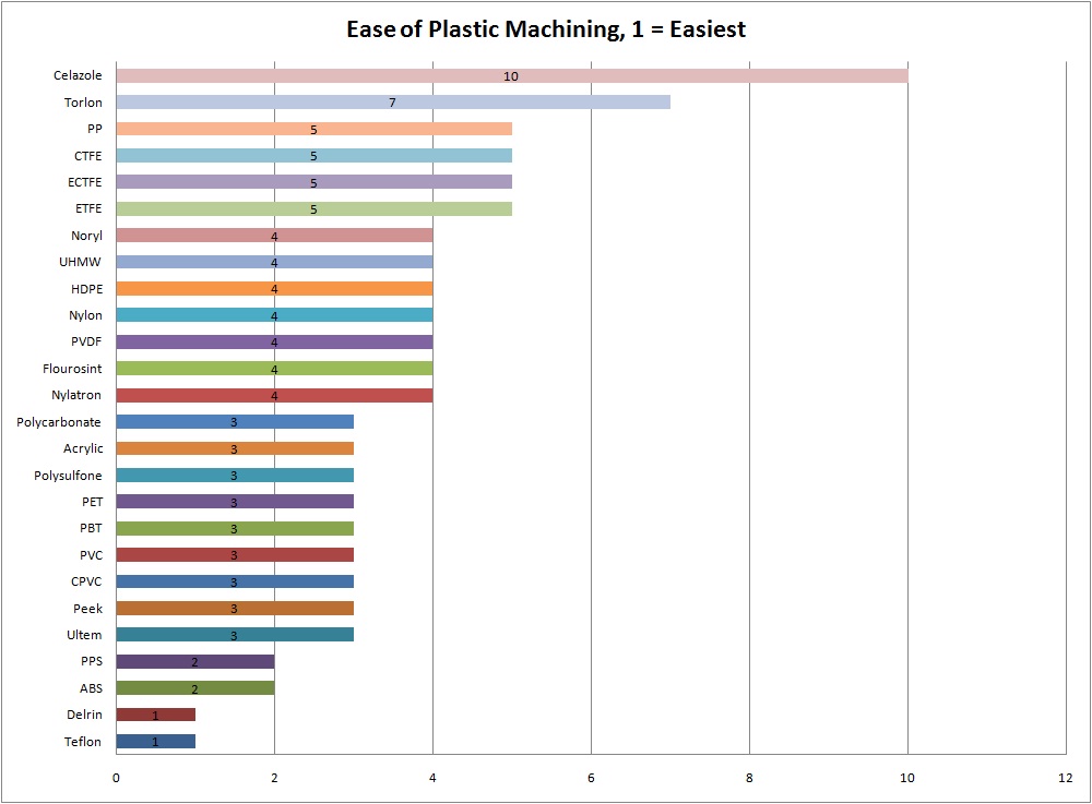
As you can see Acetal (Delrin) is one of the most machinable plastics and nylon is four times less machinable (which is why it should usually be avoided!).
Example 4: Calculate the speed and feed for a 1″ diameter, 6 flute HSS annular cutter in ¼ thick aluminum on a manual milling machine in the lab.
First, lookup the recommended surface speed in Table 1 (V ≈ 250 ft/min) and calculate the spindle speed from Equation 2:
Note that these speed and feed values are guidelines assuming adequate (flooded) lubrication and workpiece stiffness. When applying oil manually (as in the lab), scale the feed and speed back to 60%, so N = 330 rpm and f = 2.0 in/min (final answer).
HSSend millSpeedsandFeedsChart
11. Standardize the size of holes, fasteners, and other screw threads as much as possible to minimize the number of drill spindles and changes.
Example 2A: Calculate the speed and feed for a 1″ diameter, 4 flute HSS endmill in aluminum using a manual milling machine in lab.
Lathe feedsandspeedsChart
CNC drilling, short for Computer Numerical Control drilling, is a mechanical process that utilizes automated machinery to precisely create holes in workpieces. drilling machines are programmed to follow specific instructions, guiding the drill bits to penetrate the material at precise locations, depths, and angles.
Note that these speed and feed values are guidelines assuming adequate (flooded) lubrication, workpiece stiffness and drill depth less than 3 drill diameters (0.75″). When applying oil manually (as in the lab), scale the feed and speed back to 60%, so N = 450 rpm and f = 3.6 in/min (final answer).
Note that these speed and feed values are guidelines assuming adequate (flooded) lubrication, workpiece stiffness and drill depth less than 3 drill diameters (0.75″). When applying oil manually (as in the lab), scale the feed and speed back to 60%, so N = 900 rpm and f = 3.6 in/min (final answer).
10. Design parts so all holes can be drilled from the smallest number of sides – ideally only one side. This simplifies tooling and minimizes handling time.
TIP2: Do not plunge an annular cutter at a feedrate less than 0.001 ipt (inch per tooth) in strain hardening materials like 304 stainless or titanium.
Note that these speed and feed values are guidelines assuming proper (flooded) lubrication, workpiece stiffness and depth of cut. When learning how to use the CNC, always start lower (around 60% on the spindle speed and feedrate override buttons) and work your way up as you gain confidence or purchase your own tools (lol).
9. Use rectangular rather than angular coordinates to designate the location of holes on milled parts. They are easier and more foolproof for the machinist to lay out the part or a drill fixture. For turning parts, the center of the part is the natural origin of the measures.
First, lookup the recommended surface speed in Table 1 (V ≈ 625 ft/min) and calculate the spindle speed from Equation 2:
Success in CNC drilling is as much about planning and design as it is about execution. If you’re unsure of anything, MakerVerse is here to help. You can upload your designs, get quotes for your parts and work with our experts to help ensure the success of your project. Ready to get started?
12. Leave space for the drilling tool. The manufacturer needs space or access from the top of the closest wall or the clearance between the tool holder and the closest wall. That means to have a 12 mm drill center to the wall or drilled depth, plus wall under 8 times the hole diameter.
Example 3: Calculate the speed and feed for a HSS countersink used to countersink a #10 clearance hole in aluminum using a manual milling machine.
Note: since applying oil manually, scale the speeds back to 60%, so NALUM ≈ 1425 rpm and NSTEEL ≈ 570 rpm (final answer). Note these are MAXIMUM values and lathe chuck safety must take precedence; spinning the lathe chuck at 570 rpm is about the upper limit of what we safely do in the lab, so for smaller or easier to machine workpieces, DO NOT EXCEED 600 RPM regardless of the calculation results, unless you are running a collet chuck.
By following these general design tips and hole design considerations, you can optimize your manufacturing process, reducing the risk of errors, breakages, and unnecessary costs. Remember that while these tips are guidelines for best practices, each project comes with unique challenges. Strive for standardization but be ready to adapt as required.
* multiply feed values in table by 0.5 for difficult to machine materials, flexible toolholding or workpieces, or lighter-duty machines*
First, lookup the recommended surface speed in Table 1 for a 1 HSS endmill cutting aluminum (V ≈ 250 ft/min) and calculate the spindle speed from Equation 2 using the aforementioned 75% speed reduction:
One of the most common operations, CNC drilling, requires careful design considerations to ensure accuracy and efficiency. In this article, we will explore essential design tips for CNC drilling that can help maximize the drilling process’s efficiency, quality, and reliability.
Note that these speed and feed values are guidelines assuming proper (flooded) lubrication, workpiece stiffness and depth of cut. When applying oil manually (as in the lab), scale the feed and speed back to 60%, so N = 570 rpm and f ≈ 18 in/min (final answer). Note also this problem assumes we peripheral milling versus plunge milling (since we never teach the students the latter in lab).


 0086-813-8127573