
Aluminum Milling Speeds For Optimal Metal Removal - aluminum milling speeds
The following links have the most up to date information on running parameters for Harvey Tool, Helical, Titan USA, and CoreHog CNC products.
I think there’s a typo in the material type cutting data chart. I believe it should display .125 not .0125 (as used in the example).
IPM Calculator
Feed rates assume a linear motion. However, there are cases in which the path takes an arc, such as in a pocket corner or a circular interpolation. Just as increasing the DOC increases the angle of engagement on a tool, so does taking a nonlinear path. For an internal corner, more of the tool is engaged and, for an external corner, less is engaged. The feed rate must be appropriately compensated for the added or lessened engagement on the tool to provide the most effective and desired IPM for the chosen application.
Other than carbides composition, cobalt content and grain size are the main parameters affecting the mechanical properties of cemented carbide. Generally speaking, toughness improves while hardness and wear resistance decrease with increasing cobalt content. On the other hand, for a certain cobalt level, hardness improves with decreasing WC grain size. Few examples of composition for some typical machining applications are provided in the next table.
Sign up to receive a monthly recap of: – The latest machining solutions – Machining tips and tricks – A recap of our most popular posts
To produce the starting powders, tungsten powder is carburized using different methods to obtain WC, then milled together with the metal binder and, possibly, with other carbides. In their typical composition, those starting powders contain between 70% and 97% of tungsten carbides, while titanium and tantalum carbides might be present between 0,5% and 20%. The cobalt content in commercial compounds varies between 3% and 25%. Other metal binders are sometimes preferred for specific applications; WC-Ni and WC-Ni-Cr systems for example are non-magnetic (as opposed to WC-Co) and are also preferred when high corrosion resistance is required. To form the so called “green part” (a part made of powdered material, already shaped but not yet sintered) the starting powders are compacted using different techniques, depending on part size and complexity: cold and hot pressing, extrusion, or metal injection molding (MIM). In all of the aforementioned techniques a fraction of wax or lubricant is added to allow sliding of the powder particles during pressing and guarantee the necessary strength to the green parts to be handled. This fraction can be very low, for hot pressing as an example, or significant, up to 7-8% in weight; that is the case for MIM. Even though there is no universally accepted classification methods for cemented carbide, different composition are usually defined based on their application. According to ISO standards, cemented carbide for tools are divided into categories (K,P,M and, more recently, N,S,H) and subgroups called grades, denominated by increasing numbers according to the cobalt content. Each grade is specific for a certain workpiece material, machining method and working condition. To each grade a particular grain size is associated. Grain size usually varies between 0,2 μm (nano) to 8 μm (extra-coarse).
It is first necessary to define each of these factors. Cutting speed, also referred to as surface speed, is the difference in speed between the tool and the workpiece, expressed in units of distance over time known as SFM (surface feet per minute). For set-ups with stationary workpieces, SFM is the speed at which a tool moves across the part in the cut. The speed difference must be calculated in set ups where the part and tool are both moving in multi-axis machining set-ups.
Let's keep in touch.We will send you interesting posts that we collect around the web, to stay up to date on vacuum furnace technologies and applications.
While speeds and feeds are common terms used in the programming of the cutter, the ideal running parameters are also influenced by a myriad of other variables. As speeds and feeds must be well-matched to be effective, the speed of the cutter is used in the calculation of the cutter’s feed rate, measured in Inches Per Minute (IPM). The other part of the equation is the chip load, or material being removed per revolution. It is important to note that chip load per tooth and chip load per tool are different:
Get clear and useful advices to decide the features you need for your next vacuum furnace.Power, isolation, pumping units, heat exchangers and much more explained in simple words for the first time.
A chip load that is too large can pack up chips in the cutter, causing poor chip evacuation and eventual breakage. A chip load that is too small can cause rubbing, chatter, tool deflection, and a poor overall cutting action. Finding the correct balance will not only allow for the most efficient cut possible, but also ensures the most efficiency in regard to tool wear. When calculating chip load per tool or IPR, the per tooth chip load is aptly multiplied by the number of flutes on the tool itself.

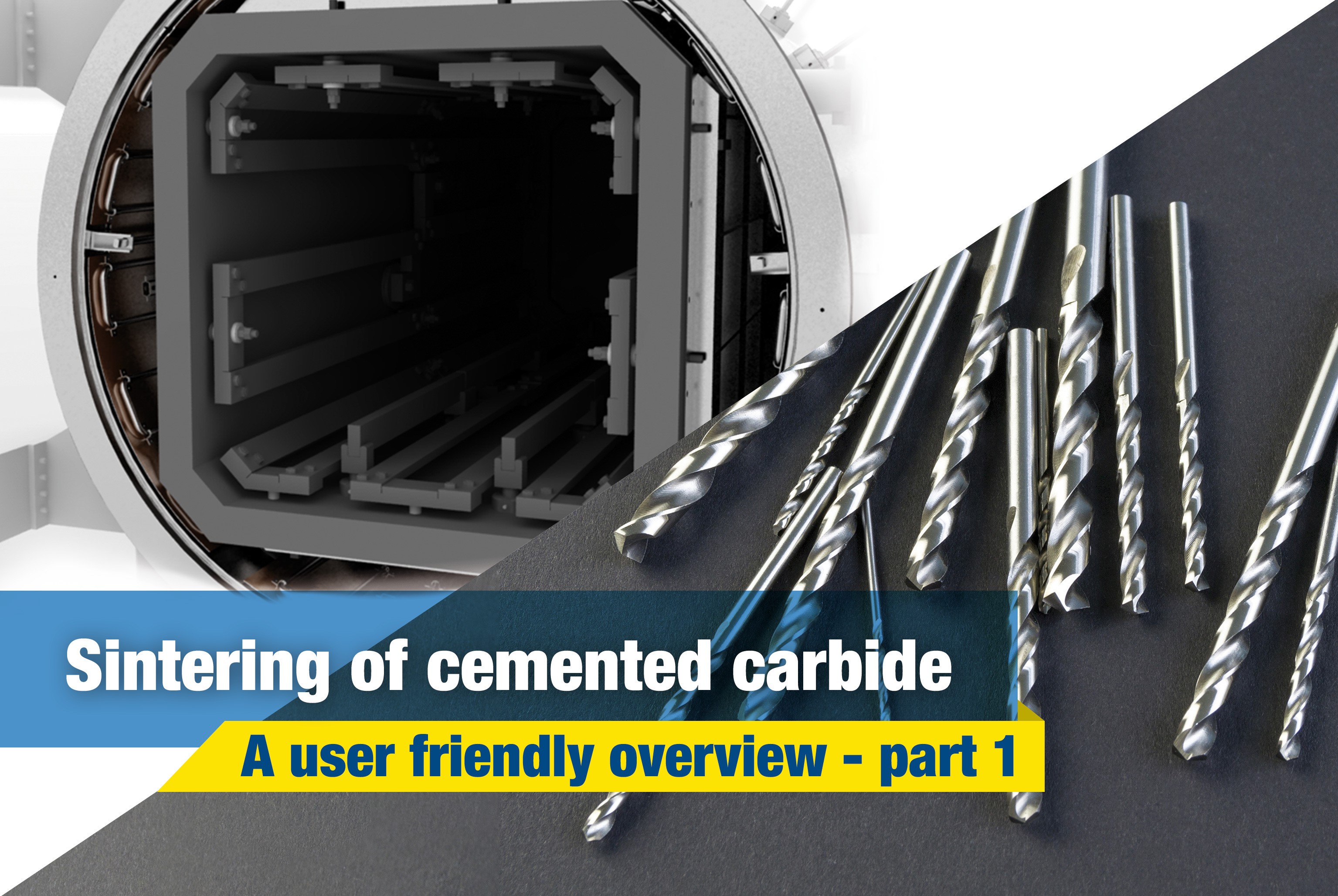
Carbide, tungsten carbide, hard metal, cemented carbide, and many other registered trademarks are often used indifferently to indicate a very popular material for the production of tools. To be precise, those terms are not exactly interchangeable. Hard metal, or cemented carbide, refers to a class of materials consisting in carbide particles dispersed inside a metal matrix. In most cases, the carbide of choice is tungsten carbide but others carbide forming element can be added, such as tantalum (in the form of TaC) or titanium (in the form of TiC). The metal matrix, often referred as “binder” (not to be confused with wax and polymers typically used in powder metallurgy) is usually cobalt, but nickel and chromium are also used. This matrix is acting as a “cement”, keeping together the carbide particles (hence the “cemented carbide” definition). To form hard metal, carbide powders are milled with the metal binder to obtain a powder that is consolidated through pressing, extrusion or metal injection molding (MIM), followed by sintering. In that sense, cemented carbide is not a metal but, more properly, a composite material. If titanium carbide prevails in the composition instead of tungsten carbide, a different material called “cermet” is formed. If the components are melted and alloyed instead of sintered, stellite is formed; a cobalt-chromium alloy containing tungsten and molybdenum. Now that we have defined cemented carbide, let’s have a look more in detail at their production process, applications and how vacuum furnaces play an essential role in that respect.
This adjustment is even more important for circular interpolation. Take, for example, a threading application involving a cutter making a circular motion about a pre-drilled hole or boss. For internal adjustment, the feed rate must be lowered to account for the additional engagement. For external adjustment, the feed rate must be increased due to less tool engagement.
It might be counterintuitive when talking about carbides, but an excess of free carbon inside the cemented carbide matrix is seriously detrimental for its properties. The tungsten-carbon-cobalt system in fact exists only when those elements have well defined proportions; too much carbon will form graphite (carbon porosities), too low carbon will form the undesirable η-phase. For that reason, controlling the dewaxing atmosphere and thermal profile is critical to ensure a complete removal of the binder at a suitable low temperature, below the “cracking” point, and avoiding both carburization and decarburization of the parts.
Depending on the wax chemical and physical properties, mainly melting point, boiling point and vapor pressure, several dewaxing methods can be applied, including both partial pressure dewaxing at few millibars or overpressure dewaxing, slightly above atmospheric pressure. In both cases, argon or hydrogen are used as process gas. For MIM parts, containing higher percentages and more complex wax-polymer systems, a solvent-dewaxing step is usually applied prior to thermal dewaxing.
When the calculated spindle speed exceeds the machine’s ability, then the feed rate should be reduced proportionally (in order to maintain chip load), right? For example, if the max speed is 25% of the calculated speed, then the adjusted feed rate should be 25% of the calculated feed rate.
on the initial feeds and speeds formulas the 3.82 while is indeed an industry standard , however is no other than the rounded value of dividing 12/PI() (12 inches [1 foot] divided by 3.14159….).
Nickel-base alloys provide outstanding resistance to specific chemicals, and some are extremely versatile and able to handle complex process and waste streams.
In the below graphic, Figure A is showcasing a linear path on a part, with a standard engagement. Figure’s B and C demonstrate the increase and decrease of engagement in non-linear, circular toolpaths. Utilizing identical feed rates between the three paths would generate three wildly different IPMs despite similar setups.
VAT IT01576210163 Share capital €3,000,000 Bergamo companies registration no. 01576210163
While many of the cutting parameters are set by the tool and workpiece material, the depths of cut taken also affect the feed rate of the tool. The depths of cuts are dictated by the operation being performed – this is often broken down into slotting, roughing, and finishing, though there are many other more specific types of operations.
An adjustment in internal feed subtracts the differences in cutter diameters from the differences in outer diameters before dividing by the outer dia. difference. On the other hand, adjusting for external feed adds the differences between cutter diameters to the differences in inner diameters before dividing by the inner dia. difference.
SFMCalculator Lathe
These unique operations utilize much different depths of cut, with industry standardized terms as description. Slotting can be described as utilizing 180° of the diameter of the tool engaged in the cut. Roughing on the other hand will typically disperse both ADOC and RDOC relatively evenly. Finally, finishing operations will use substantially more axial depths of cut in relation to radial, leaving the best finish possible on the workpiece.
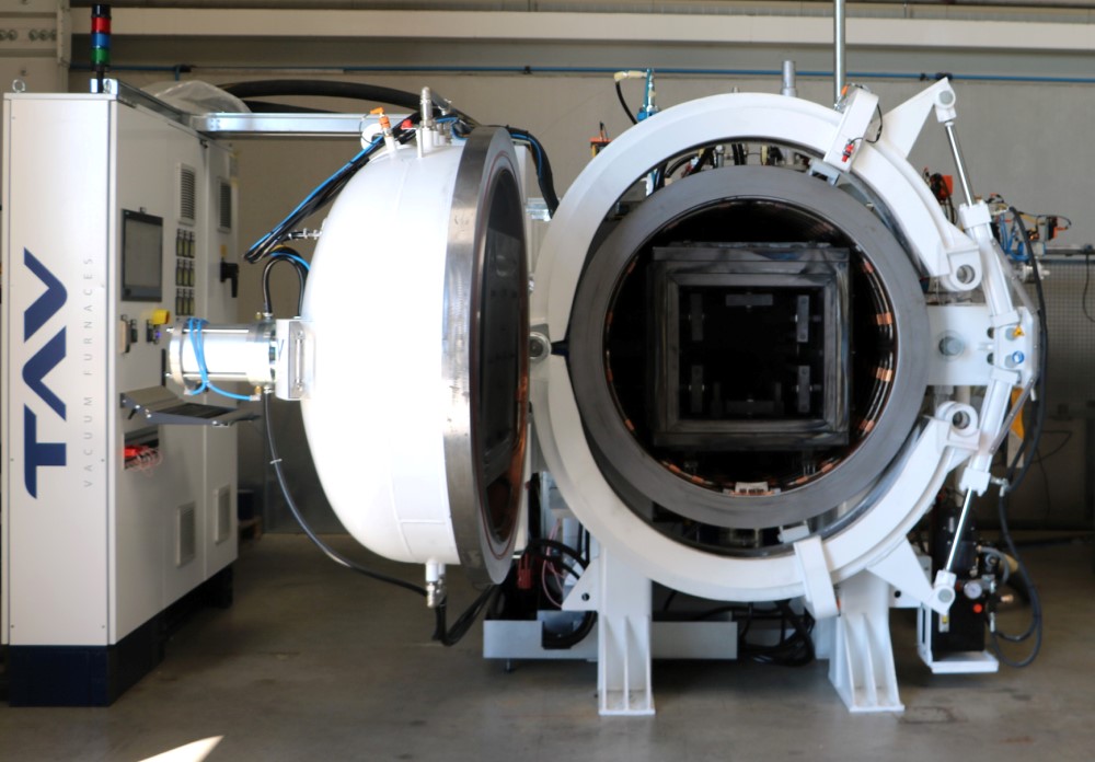
After powder compaction, the parts are ready to be sintered, which is necessary to consolidate the starting powder into parts with high density.
Additionally, at TAV VACUUM FURNACES we use our DST (Double Sealing Technology) on hydrogen furnaces to completely eliminate any possibility of leaks on all of the flanges, including the door. Finally, a safety PLC and redundant instrumentation ensures that all the relevant parameters are inside the operational safety level.
Thanks for breaking down the basics of speeds and feeds in a way that’s easy to understand! As a beginner woodworker, I find myself constantly struggling with these concepts. Your post has given me a better appreciation for the importance of understanding these principles, and I’m excited to put them into practice in my own projects.
These calculations are useful guidelines for running a cutting tool optimally in various applications and materials. However, the tool manufacturer’s recommended parameters are the best place to start for initial numbers and to set a baseline for the best tool performance. After that, it is up to the machinist’s eyes, ears, and experience to help determine the best running parameters, which will vary by set-up, tool, machine, and chosen material. No operation is exactly the same, and nothing occurs in a vacuum. Experience and continued learning will always aid machinists in ensuring the most efficient performance possible in the cut.
Sep 29, 2024 — Adiseal Ultimate metal drill bits and masonry drill bits were found to be the best drill bits in our tests. They were found to be the most ...
Many tooling manufacturers provide useful speeds and feeds charts calculated specifically for their products. For example, Harvey Tool provides the following chart for a 1/8” diameter end mill, tool #50308. A customer can find the SFM for the material on the left, in this case 304 stainless steel (highlighted in yellow). The chip load (per tooth) can be found by intersecting the tool diameter on the top (blue heading) with the material and operations (based on axial and radial depth of cut), highlighted in the image below.
SFM toIPM
As shown above, the cutter speed (RPM) is defined by the SFM (based on material) and the cutter diameter. With miniature tooling and/or certain materials the speed calculation sometimes yields an unrealistic spindle speed. For example, a .047” cutter in 6061 aluminum (SFM 1,000) would return a speed of ~81,000 RPM. Since this speed is only attainable with high speed air spindles, the full SFM of 1,000 may not be achievable. In a case like this, it is recommended that the tool is run at the machine’s max speed (that the machinist is comfortable with) and that the appropriate chip load for the diameter is maintained. This produces optimal parameters based on the machine’s top speed. All machines are unique and provide different max speed, therefore these calculations will vary from machine to machine.
Photographs, videos, graphics and texts of TAV VACUUM FURNACES are licensed under license Creative Commons Attribution-NonCommercial-No derivative works 3.0 Unported License.
Adorable Chihuahua puppies await in Syracuse, NY! Personal pickups only, no shipping. Visit or contact us for a joyful puppy-buying experience.
Material Removal Rate (MRR), while not part of the cutting tool’s program, is a helpful way to calculate a tool’s efficiency. MRR takes into account two very important running parameters: Axial Depth of Cut (ADOC), or the distance a tool engages a workpiece along its centerline, and Radial Depth of Cut (RDOC), or the distance a tool is stepping over into a workpiece. The MRR calculation (seen below) relies on the calculated feed rate. The feed rate (IPM) is multiplied by the radial and axial depths of cut to produce the rate of removal.
www.harveytool.com www.helicaltool.com www.micro100.com www.titancuttingtools.com www.corehog.com www.valorholemaking.com
SFM toRPM Drilling calculator
Be sure not to miss the second part of the article, where we will discuss about vacuum sintering and sinter-HIP of cemented carbide, as well as the equipment dedicated to those processes!
Before using a cutting tool, it is necessary to understand tool cutting speeds and feed rates, more often referred to as “speeds and feeds.” Speeds and feeds are the cutting variables used in every milling operation and vary for each tool based on cutter diameter, operation, material, etc. Understanding the right speeds and feeds for your tool and operation before you start machining is critical. These are to be used to set baselines for a particular tool, ensuring proper performance without compromising part finish and tool life.
IPRtoIPM calculator
Types of CNC Cutting Tools (With Illustrations) · #1 Drill Bits · #2 End Mill · #3 Face Mill · #4 Reamers · #5 Gear Cutters · #6 Hollow Mill · #7 Thread Mill · #8 Slab ...
I like that you mention how the right high-speed air spindles are needed to get the ones that match the calculations. When choosing the components, it would probably be a good idea to ensure you choose the right supplier. This could help you get custom machine spindles and other components that fit your equipment correctly to match the speeds or other aspects that you want.
Suitable wax trapping systems must be used to protect the vacuum pumps from contaminations, in the case of partial pressure dewaxing, or to condense most of the volatile organic compound before they can reach the afterburner at the furnace outlet, in the case of overpressure dewaxing. Moreover, a heated jacket can be fitted to pipe connecting the furnace to the wax trap, to prevent condensation of wax before the trap inlet and obstruction of the pipe in the long term.
SFM is based on the various properties of the given material. Speed, referred to as Rotations Per Minute (RPM) is based off of the SFM and the cutting tool’s diameter. As SFM is tied to the properties of a material, it does not change based upon the operation being performed and remains constant despite changes in chip load calculation. The SFM calculation utilizes the industry standard of 3.82. Here, the cutter diameter of the chosen tool is multiplied by the speed or RPM. This figure is then divided by 3.82 to generate the SFM or Surface Feet per Minute.
Furnaces operating with hydrogen overpressure requires additional systems and safeties, including an electrically or gas fired afterburner to prevent hydrogen accumulation in a confined area.
Feb 2, 2024 — The Caboose cutter in Barbados is reason enough to go back.
Hi Scott! Thanks for your feedback and question. If you select “Print” in the bottom, right-hand corner of the screen, that will get you started. Then, change the “Destination” field to “Save as PDF.” Hopefully that works for you – Please let us know if you have any other questions.
Each operation recommends a unique chip load per the depths of cut depending on the operation, thus resulting in different feed rates for the desired application. Since the SFM is based on the material, it will always remain constant for each of the three defined operations.
Looking for automotive solutions? Reduce your costs using new procedures and processes.
SFMCalculator turning
The following table calculates the speeds and feeds for this tool (#50308) and material (304 Stainless) for each operation, based on the chart above:
Adjusting depths of cut can decrease time in cut and overall production time, freeing up machines for additional manufacturing. An example of depth of cut adjustment is seen in High Efficiency Milling, where RDOC is decreased and ADOC is increased. In this method, MRR is increased while also reducing tool wear, leading to higher productivity and more parts per tool.
Great question! Yes, if your machine has a limitation and your calculated spindle speed (RPM) is higher than this limitation, you would need to recalculate the feed rate using the spindle speed (RPM) that works in your machine.
It is a constant, maybe not industry, but it is a constant because it is a math conversion and is always the same. Therefore it IS a constant and it is used mostly in the manufacturing and machining industry. So in conclusion, yes, it is an industry used constant
The tool’s depth of cuts and the rate at which it is cutting can be used to calculate how many cubic inches per minute (in3/min) are being removed from a workpiece. This equation is extremely useful for comparing cutting tools and examining how cycle times can be improved. Decreased cycle times leads to higher productivity within a shop, which is what all machinists aim for during production.
On angled tools the cutter diameter changes along the LOC. For example, Helical tool #07001, a flat-ended chamfer cutter with helical flutes, has a tip diameter of .060” and a major/shank diameter of .250”. In a scenario where it was being used to create a 60° edge break, the actual cutting action would happen somewhere between the tip and major/shank diameters. To compensate, the equation below can be used to find the average diameter along the chamfer.
Good Quality CNC Milling Inserts Supplier & Wholesale CNC Milling Inserts From China - Chengdu Metcera Advanced Materials Co.,ltd.
SFM toRPM Calculator
The first step of the consolidation process is always dewaxing. As already mentioned, cemented carbide green parts contain a certain amount of wax/lubricant, often paraffin or PEG, that must be removed before heating the parts to the sintering temperature. Incomplete dewaxing before sintering can lead to the formation of entrapped gas porosity, coming from the evolution of wax vapours inside the parts, and carbon residuals.
Century Tool Metric Pitch Thread Gauge, 12-40 Thread Sizes, Model# 98402.
You’re missing the point entirely. Of course the value is constant, but it shouldn’t be treated as a magic number (aka “industry standard”). Instead, the source of the rounded value should be explained, so people don’t have to try and remember yet another obscure number (it’s not like it helps you do the math in your head either if you round it). It’s 12 divided by PI.
RPMtoinches per minute Calculator
I totally agree. 3.82 is not an “industry constant”. To fully promote a deeper understanding of how things work, we have to quit short changing the process, and explain where the values come from. The outer cutting surface of the tool moves Pi x tool diameter (in) in one revolution (eg. the equation of the circumference of a circle). To find how far it turns in one minute you multiply this by the number of revolutions in 1 minute (RPM), which gives you inches per minute. To convert that to feet per minute, you must divide by 12 inches in 1 foot. This gives you Tool Dia (in) x Pi (3.14159) x RPM/12. Taking the 12 and dividing by Pi gives you the 3.82, and the equation reduces to SFM=Tool Dia (in) x RPM/3.82.
Take this example, in which a Harvey Tool threadmill #70094, with a .370” cutter diameter, is machining a 9/16-18 internal thread in 17-4 stainless steel. The calculated speed is 2,064 RPM and the linear feed is 8.3 IPM. The thread diameter of a 9/16 thread is .562”, which is used for the inner and outer diameter in both adjustments. After plugging these values into the equations below, the adjusted internal feed becomes 2.8 IMP, while the external feed becomes 13.8 IPM.
Chipload Data ... The chip load is the measurement of the thickness of material removed by each cutting edge during a cut. This is a valuable piece of information ...
Using this calculation, the effective cutter diameter is .155”, which would be used for all Speeds and Feeds calculations.
Great post! I found it really interesting to learn about the relationship between cutting speed and feed rate in machining. As a beginner machinist, I’ve been struggling to find the right balance between these factors to achieve the desired results. This post has helped me understand the principles behind it and I can’t wait to try out some of the techniques you’ve mentioned. Thanks for sharing!
Solid Carbide Ball Nose End Mill TOP-Cut. 3825A. without chip breaker. Ball nose (full radius). Recommended feed directions of the respective cutters.
ATI MARKETING is the well known Exporter, Importer, Trader, Supplier of Vardex Threading Inserts based in Mumbai, Maharashtra, India.
TAV VACUUM FURNACES SPA Via dell’Industria 11 24043 Caravaggio (BG) Italy


 0086-813-8127573