
Ball End Mill Sizes: Guide to Choosing the Right Diameter - common end mill sizes
As we said in the lesson, the first letter identifies the shape of the insert; in this case is triangular with an angle between the cutting edges of 60 degrees.
The first pair equals to 16 mm: this is the length of the insert side. With the triangular shape there are also other lengths, for example 11 or 22mm. The side dimension is 16 mm, which corresponds to an inscribed circle of 9.525 mm. This number was used to calculate the numerical value of tolerance M.
Good morning, in today’s additional info I would like to give you some examples of ISO nomenclature in order to help you become familiar with the names of the inserts but above all with the coding itself. It is very important for anyone working in machining to know and understand the insert and its ISO nomenclature. In the lesson we saw three examples of ISO nomenclature when we asked Paolo the question; we saw an RNMG, a WNMG and a WCGT. Apart from the first letter which distinguishes the form, the first two inserts have identical parameters 2, 3 and 4 and exactly _NMG. This is also the most common ISO nomenclature for double-sided tools with chipbreaker geometry; these, as we shall see in the lesson on side rake angles, are fitted to negative tools. While the third case of the exercise posed to Paolo has parameters 2, 3 and 4 equal, _CGT. The latter is the most common ISO nomenclature for single-sided inserts. Let’s look at a new case very similar to the one seen in the lesson. TNMG 160404 PF So let’s go in order and start with the letter T. Insert shape As we said in the lesson, the first letter identifies the shape of the insert; in this case is triangular with an angle between the cutting edges of 60 degrees. Side rake angle The second letter determines the value of the insert clearance angle. N for the ISO is an angle of 0 degrees so our insert can be a double-sided insert, so it can be used on both sides. It should also be noted at this point that the fixing of the insert on the tool is of the lever type and therefore a strong fixing. Tolerance Then we come to the third letter M. M establishes the tolerance class that is given with respect to the circle inscribed in the geometric figure of the insert. In this case is a circle with a diameter of 9.525. This value, the diameter of the inscribed circle, is taken from the insert size table, which we will see with parameter 5 relating to the size. Class M is a tolerance that is not very precise but nevertheless one of the most widely used in turning and which corresponds exactly to ±0.05 mm. Insert type Let’s now move on to G, the last letter of the alphanumeric code; it indicates that our insert has a chip-breaking geometry on the face of the cutting edge, suitable for controlling and breaking the chips that will be formed during machining. Obviously, the geometry is studied and carried out on both faces of the insert. Moreover it has some characteristics in relation to the material to be machined and the operation to be carried out, i.e. finishing or roughing of a component. After the letters we now move on to the numbers, which as we have seen are taken in pairs. Size The first pair equals to 16 mm: this is the length of the insert side. With the triangular shape there are also other lengths, for example 11 or 22mm. The side dimension is 16 mm, which corresponds to an inscribed circle of 9.525 mm. This number was used to calculate the numerical value of tolerance M. Thickness The length of the cutting edge will influence the removal capacity of the insert depending on the thickness. This thickness is determined by the second pair of numbers, which we see here as 04. This pair indicates a thickness of 4.76 mm from the inch-millimetre conversion. Other cutting edge lengths will have different thicknesses. Please note that thickness is very important as it constitutes the resistant section of the cutting edge. The greater the thickness, the greater the strength of our insert. Sometimes, in order to increase the life of the cutting edge with the same chip volume, i.e. with the same working data, it is sufficient to oversize the length of the cutting edge. This will provide a higher thickness, which will guarantee high resistance to the cutting forces and temperatures that will develop during turning. Nose radius The third and last pair of numbers in this part is 04, which in tenths of a millimetre is the value of the nose radius. The nose radius influences the strength of the cutting edge. In fact, a radius such as in this case 0.4 mm cannot be used for heavy roughing operations where, on the contrary, a larger radius will be useful, for example 1.2 mm. Therefore, this value of 0.4 mm also means that the field of application for this insert will be finishing or other light operations. The last parameter to be considered is the pair of letters which in this case is PF. The field n°12 is left empty by the ISO standard for the insert builder who uses it to indicate the geometry of the chipbreaker drawn on the insert face. This geometry is fundamental for a correct use of the insert. In fact, each geometry has been designed and studied to control chip formation in precise applications. These applications vary in terms of material groups and type of machining: finishing, medium removal or roughing. In our case we have used the letters PF as an example, where P identifies the family of steels while F indicates the finishing operation. So in this case the chipbreaker geometry is suitable for finishing operations on steels. To conclude, we can say that knowing the insert nomenclature you will have identified every dimensional and constructional aspect of your insert. Only the geometry of the chip breaker will be excluded from ISO, since it is not included in the standard and is defined differently from builder to builder. TPGN 110308 This second example of an insert is not very common, but it is shown here for educational purposes. It is a turning and finishing insert that is assembled on boring bars for internal machining or on adjustable boring cartridges. The insert has a flat face and its fixing system is of the micro-fused bracket type. T = triangular-shaped insert P = 11 degree insert clearance angle G = tolerance class in this case of accuracy N = insert with a flat face without chipbreaker geometry 11 in millimetres is the length of the side of the insert 03 indicates the thickness S of the product, here set at 3.17 millimetres 08 in tenths of a millimetre is the value of the nose radius which in this case is 0.8mm SOEX 120508 Again, this is an uncommon insert but ideal for understanding the ISO nomenclature. It is a screw-clamp type insert with a countersunk slot, used in finishing or semi-finishing operations on internal machining tools such as boring bars. Sometimes for some builders it is also used in drilling on mechanically clamped drills. S = square-shaped insert O = 8 degree insert clearance angle E = tolerance class on inscribed circle. Precision insert (inscribed circle equal to mm 12,70) X = special non ISO standard (this letter only) with chipbreaker geometry 12 = in mm insert side length mm 12 05 = thickness value, in this case is 5.16mm 08 = in tenths of a millimetre the value of the nose radius, in this case 0.8mm CHOICE OF NOSE RADIUS Now that we have seen some examples of coding that have been more or less used, let’s say a few words about the choice of the insert nose radius. The nose radius influences a very important cutting data, the feed rate. We will dedicate a specific lesson to the feed rate, but for the moment let’s say that it identifies the speed at which the tool carries out its removal path. To be precise in turning operations, it is measured in mm per revolution, i.e. the distance covered by the tip of the insert at each turn of the workpiece. The values, as we shall see, range from a few hundredths of a millimetre to a few millimetres in the rarest cases. A small nose radius implies small feeds; large nose radius allows large feeds to be used. When choosing the radius of the point we must take into account various aspects which I will list below: In finishing operations the nose radius influences the internal corner radius that will remain on the workpiece profile. So it is usually the design or construction guidelines of the workpiece that define the maximum insert corner radius. Usually the most commonly used radius that takes this into account is 0.4mm. Obviously, if your workpiece has no internal corner radius or the value of the internal radius left on the workpiece is irrelevant, the choice of insert radius will be made on the basis of the following considerations; Larger nose radius, stronger inserts; With large nose radius, high feed rates are possible (more on this in the feed rate lesson); Adopting large nose radius (all other cutting parameters being equal) will develop more radial forces, which are one of the primary sources of vibration. This last aspect is the one that puts a limit on the maximum nose radius that can be used. We will return to this subject in future lessons.
It was helpful when you said to choose the right tooling. My husband was telling me yesterday afternoon at lunch about how he plans on finding a disturb for stainless steel at his work in a couple of weeks. I’ll pass these tips along to him so he can know more about working with stainless steel properly.
Stainless steel can be as common as Aluminum in many shops, especially when manufacturing parts for the aerospace and automotive industries. It is a fairly versatile material with many different alloys and grades which can accommodate a wide variety of applications. However, milling steel can also be immensely difficult. Stainless steels are notorious end mill assassins, so dialing in your speeds and feeds and selecting the proper tool is essential for machining success.
Then we come to the third letter M. M establishes the tolerance class that is given with respect to the circle inscribed in the geometric figure of the insert. In this case is a circle with a diameter of 9.525. This value, the diameter of the inscribed circle, is taken from the insert size table, which we will see with parameter 5 relating to the size. Class M is a tolerance that is not very precise but nevertheless one of the most widely used in turning and which corresponds exactly to ±0.05 mm.
ISO turninginsertnomenclature
Sign up to receive a monthly recap of: – The latest machining solutions – Machining tips and tricks – A recap of our most popular posts
Generally speaking, when machining stainless steels a SFM of between 100-350 is recommended, with a chip load ranging between .0005” for a 1/8” end mill up to .006” for a 1” end mill. A full breakdown of these general guidelines is available here.
Stainless steels are high-alloy steels with superior corrosion resistance to carbon and low-alloy steels. This is largely due to their high chromium content, with most grades of stainless steel alloys containing at least 10% of the element.
To be precise in turning operations, it is measured in mm per revolution, i.e. the distance covered by the tip of the insert at each turn of the workpiece. The values, as we shall see, range from a few hundredths of a millimetre to a few millimetres in the rarest cases. A small nose radius implies small feeds; large nose radius allows large feeds to be used.
It seems like HEV-5 is better for my project. I need to get a new CNC machine for the warehouse. I’ll have to get something with a remote power source.
It’s awesome that stainless steel is designed to resist corrosion due to their high chromium content. My boss has been telling me about how he wants to build a new machine this quarter for use outside, and he wants to make sure that it can stand up to the weather. I’ll pass this information along to him so that he can look further into his options for using stainless steel.
Machining Advisor Pro is a cutting edge resource designed to precisely calculate running parameters for high performance Helical Solutions end mills in materials like stainless steel, aluminum, and much more. Simply input your tool, your exact material grade, and machine setup and Machining Advisor Pro will generate fully customizable running parameters. This free resource allows you to push your tools harder, faster, and smarter to truly dominate the competition.

Carbide insertidentification chart PDF
Now that we have seen some examples of coding that have been more or less used, let’s say a few words about the choice of the insert nose radius.
Again, this is an uncommon insert but ideal for understanding the ISO nomenclature. It is a screw-clamp type insert with a countersunk slot, used in finishing or semi-finishing operations on internal machining tools such as boring bars. Sometimes for some builders it is also used in drilling on mechanically clamped drills.
Milling insertspecification
Stainless steel can be broken out into one of five categories: Austenitic, Ferritic, Martensitic, Precipitation Hardened (PH), and Duplex. In each category, there is one basic, general purpose alloy. From there, small changes in composition are made to the base in order to create specific properties for various applications.
To conclude, we can say that knowing the insert nomenclature you will have identified every dimensional and constructional aspect of your insert. Only the geometry of the chip breaker will be excluded from ISO, since it is not included in the standard and is defined differently from builder to builder.
Insert designationchart
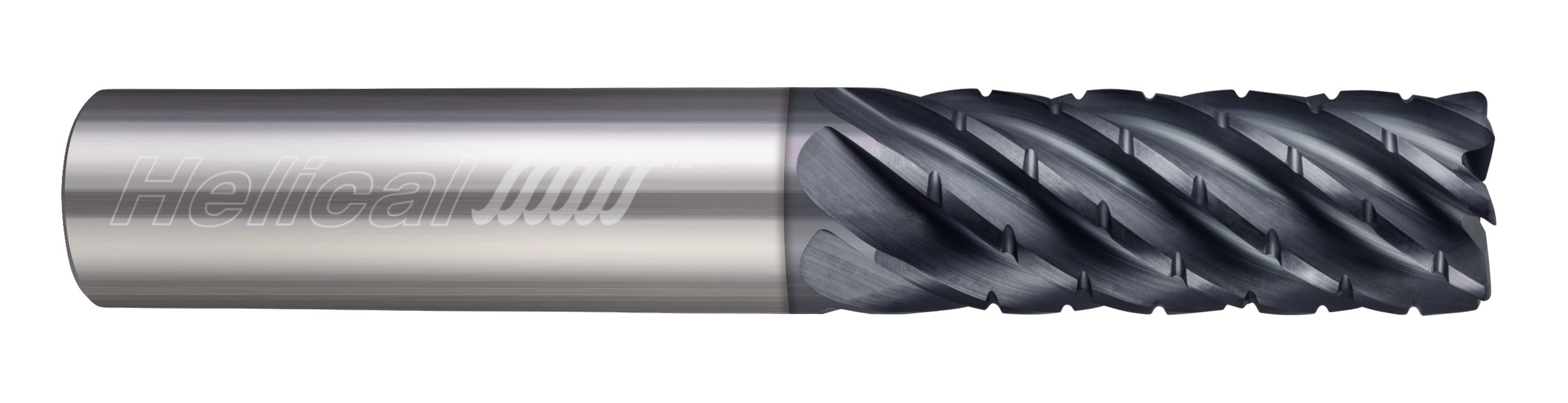
High Efficiency Milling (HEM) can be a very effective machining technique in stainless steels if the correct tools are selected. Chipbreaker roughers would make an excellent choice, in either 5 or 7 flute styles, while standard 5-7 flute, variable pitch end mills can also perform well in HEM toolpaths.
Second, when you are looking to use a machine on the surface of the steel, it is important that you use the right tool for the job. For example, if you are going to be working on a soft steel, then you should not use a drill or a shredder, because these will likely scratch the surface of the material, making the entire thing less resistant to the processes that you are having done. Instead, you will want to use a special type of saw, one that cuts slits into the metal at different angles, in order to make small holes, rather than drilling the entire thing. This Slaying Stainless Steel: Machining Guide tip should help you with this, so that you can get the most accurate results from the equipment that you are using.
I like how you said that stainless steel cookware can be seasoned and sealed to be more easily cleaned just like cast iron can be. My wife and I would really like to have some good nonstick pans. We’ll have to look into getting some good cookware that will give us those benefits, or that we can add the benefits to.
The axial engagement of a tool in a slotting operation should be suitable for the specific tool employed, as depicted in Figure 3. Employing an unsuitable method may result in tool deflection, potential damage, and compromised part quality. Chip evacuation is going to be key for slotting in stainless steel. For this reason, 4 flute tools are the best choice because the lower flute count allows for more efficient chip evacuation. Tools with chipbreaker geometry also make for effective slotting in stainless steel, as the smaller chips are easier to evacuate from the cut.
Good morning, in today’s additional info I would like to give you some examples of ISO nomenclature in order to help you become familiar with the names of the inserts but above all with the coding itself. It is very important for anyone working in machining to know and understand the insert and its ISO nomenclature.
In fact, each geometry has been designed and studied to control chip formation in precise applications. These applications vary in terms of material groups and type of machining: finishing, medium removal or roughing. In our case we have used the letters PF as an example, where P identifies the family of steels while F indicates the finishing operation. So in this case the chipbreaker geometry is suitable for finishing operations on steels.
Stainless steel machining doesn’t have to be hard. By identifying the proper material grade for each part, selecting the perfect cutting tool, and optimizing running parameters, headaches from milling steel can become a thing of the past.
Carbide insertmaterial chart
Please note that thickness is very important as it constitutes the resistant section of the cutting edge. The greater the thickness, the greater the strength of our insert. Sometimes, in order to increase the life of the cutting edge with the same chip volume, i.e. with the same working data, it is sufficient to oversize the length of the cutting edge. This will provide a higher thickness, which will guarantee high resistance to the cutting forces and temperatures that will develop during turning.
In the lesson we saw three examples of ISO nomenclature when we asked Paolo the question; we saw an RNMG, a WNMG and a WCGT. Apart from the first letter which distinguishes the form, the first two inserts have identical parameters 2, 3 and 4 and exactly _NMG. This is also the most common ISO nomenclature for double-sided tools with chipbreaker geometry; these, as we shall see in the lesson on side rake angles, are fitted to negative tools. While the third case of the exercise posed to Paolo has parameters 2, 3 and 4 equal, _CGT. The latter is the most common ISO nomenclature for single-sided inserts.
The nose radius influences a very important cutting data, the feed rate. We will dedicate a specific lesson to the feed rate, but for the moment let’s say that it identifies the speed at which the tool carries out its removal path.
This is really very very interesting and informative too, You contain a lot of information in a single article regarding this, Thank you for sharing your knowledge. Keep updating us with your knowledge.
I was looking for this information relating to slaying stainless steel: machining guide. You have really eased my work, loved your writing skill as well. I like how you have researched and presented these exact points so clearly. Please keep sharing more!
I have a need for a 6.5 inch long 11/64ths (.171 inch) end mill or drill/mill that I can use to drill holes in steel then begin the side-to-side milling process. I do engraving work and I sometimes need to make my own jigs to hold various items to be engraved. I made my own drill tool using one of my broken cutters and it worked, but I am certain there has to be a better more efficient way of doing business.
While tool selection is a critical step to more effective machining, dialing in the proper running parameters is equally important. There are many factors that go into determining the running parameters for stainless steel machining, but there are some general guidelines to follow as a starting point.
The last parameter to be considered is the pair of letters which in this case is PF. The field n°12 is left empty by the ISO standard for the insert builder who uses it to indicate the geometry of the chipbreaker drawn on the insert face. This geometry is fundamental for a correct use of the insert.
ISOinsertnomenclature pdf
I would recommend giving our tech team a call to talk through this application and see how we can help. You can reach them by calling 800-645-5609 or by emailing to [email protected]
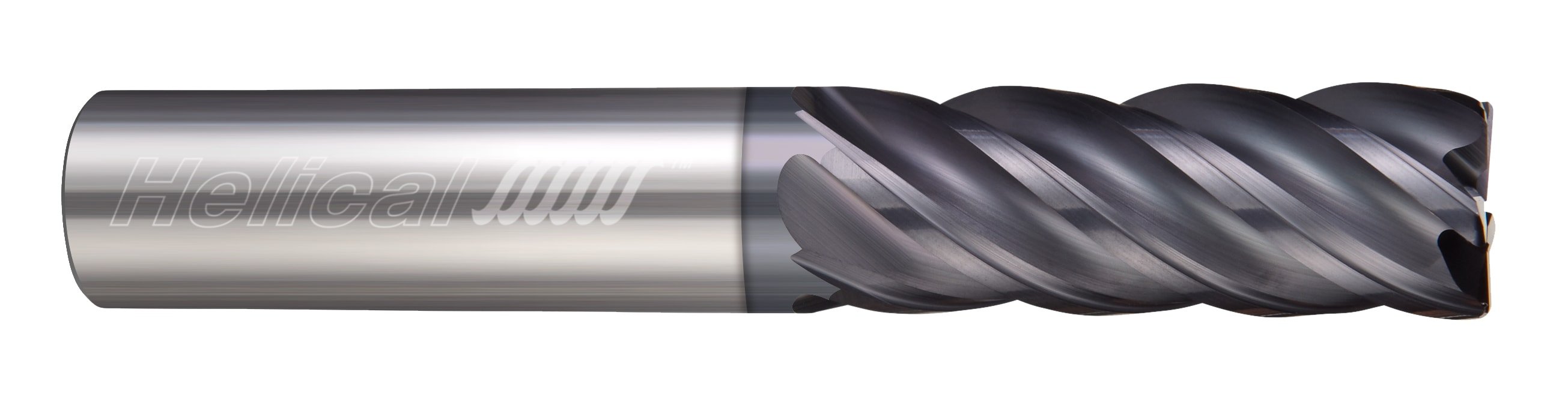
For traditional roughing, a 4 or 5 flute end mill is recommended. 5 flute end mills will allow for higher feed rates than their 4 flute counterparts, but either style would work well for roughing applications. Below is an excellent example of traditional roughing in 17-4 Stainless Steel.
When finishing stainless steel parts, a high flute count and/or high helix is required for the best results. Finishing end mills for stainless steel will have a helix angle over 40 degrees, and a flute count of 5 or more. For more aggressive finishing toolpaths, flute count can range from 7 flutes to as high as 14. Below is a great example of a finishing run in 17-4 Stainless Steel.
Let’s now move on to G, the last letter of the alphanumeric code; it indicates that our insert has a chip-breaking geometry on the face of the cutting edge, suitable for controlling and breaking the chips that will be formed during machining. Obviously, the geometry is studied and carried out on both faces of the insert. Moreover it has some characteristics in relation to the material to be machined and the operation to be carried out, i.e. finishing or roughing of a component.
ISOinsertgrade chart
The second letter determines the value of the insert clearance angle. N for the ISO is an angle of 0 degrees so our insert can be a double-sided insert, so it can be used on both sides. It should also be noted at this point that the fixing of the insert on the tool is of the lever type and therefore a strong fixing.
www.harveytool.com www.helicaltool.com www.micro100.com www.titancuttingtools.com www.corehog.com www.valorholemaking.com
Carbide insertcodes explained
I appreciate what you said about using a 5 flute end. My office needs some steel sheets milled out. I’ll have to have a manufacturer design something to my specifications.
This second example of an insert is not very common, but it is shown here for educational purposes. It is a turning and finishing insert that is assembled on boring bars for internal machining or on adjustable boring cartridges. The insert has a flat face and its fixing system is of the micro-fused bracket type.
The length of the cutting edge will influence the removal capacity of the insert depending on the thickness. This thickness is determined by the second pair of numbers, which we see here as 04. This pair indicates a thickness of 4.76 mm from the inch-millimetre conversion. Other cutting edge lengths will have different thicknesses.
Helical Solutions offers the HEV-5 end mill, which is an extremely versatile tool for a variety of applications. The HEV-5 excels in finishing and HEM toolpaths, and also performs well above average in slotting and traditional roughing. Available in square, corner radius, and long reach styles, this well-rounded tool is an excellent choice to kickstart your tool crib and optimize it for stainless steel machining.
For reference, here are the properties of each of these groupings, as well as a few examples of the popular grades and their common uses.
The third and last pair of numbers in this part is 04, which in tenths of a millimetre is the value of the nose radius. The nose radius influences the strength of the cutting edge. In fact, a radius such as in this case 0.4 mm cannot be used for heavy roughing operations where, on the contrary, a larger radius will be useful, for example 1.2 mm. Therefore, this value of 0.4 mm also means that the field of application for this insert will be finishing or other light operations.
Choosing the correct tooling for your application is crucial when machining stainless steel. Roughing, finishing, slotting, and high efficiency milling toolpaths can all be optimized for stainless steel by choosing the correct style of end mill.
First off, you should know the difference between hard and soft steel. Hard steel is often used for things like bicycles and cars, while soft steel is usually what you will find used in machining. If you need a lot of precision, then you will probably want to get the hard steel, since it is often much more durable and better able to withstand the pressure that you are going to be putting on it. However, if you do not have a lot of extra money to spend, then you may want to consider soft steel, because it will still stand up to the pressure of the job, but it is not as dense as hard steel.


 0086-813-8127573