
Best Drill Bits For Concrete - the best drill bits
To assess stability, rate it on a scale of 0 to 10, where 10 represents a perfectly stable setup with a short tool overhang, and 0 represents a poor setup. Adjust the speed according to the factors from the chart provided (assuming that the catalog recommendation refers to a score of 8).
Feed per tooth formulaexcel
The feed (milling machine feed) can be defined as the distance in inches per minute that the work moves into the cutter.
Feed per tooth, is the amount of material that should be removed by each tooth of the cutter as it revolves and advances into the work.
Feed per tooth formulacalculator
It is important to remember that the information presented here is not purely scientific. Nonetheless, it can be a useful guide for adjusting cutting speeds based on application conditions.
Feed per toothtoFeed perrevolution calculator
This chip thickness or feed per tooth, along with the number of teeth in the cutter, form the basis for determining the rate of feed.
The hardness of the cutting tool material will also have a great deal to do with the recommended cutting speed. The harder the drill, the faster the cutting speed. The softer the drill, the slower the recommended cutting speed (See Figure 2).
Feed per tooth formulain mm
When drilling and tapping, it is crucial to use oil. It keeps the bits from squealing, makes the cut smoother, cleans out the chips, and keeps the drill and stock from overheating.
Cutting tool suppliers provide recommendations for cutting speed, but these are broad and intended for perfect conditions. These recommendations are too high in many cases, and we need to adjust them for our specific application. We can use speeds and feeds calculators or the Seco Assistant. However, understanding the parameters influencing calculations will enable better decision-making, longer tool life, and higher productivity.
feed per toothto mm/min calculator
Once the SFM for a given material and tool is determined, the spindle can be calculated since this value is dependent on cutting speed and tool diameter.
On the milling machines we have here at LBCC, the feed is independent of the spindle speed. This is a good arrangement and it permits faster feeds for larger, slowly rotating cutters.
Manufacturing Processes 4-5 Copyright © by LamNgeun Virasak is licensed under a Creative Commons Attribution 4.0 International License, except where otherwise noted.
Pecking helps ensure that bits don’t overheat and break when using them to drill or tap. Peck drilling involves drilling partway through a part, then retracting it to remove chips, simultaneously allowing the piece to cool. Rotating the handle a full turn then back a half turn is common practice. Whenever the bit or tap is backed out, remove as many chips as possible and add oil to the surface between the drill or tap and the workpiece.
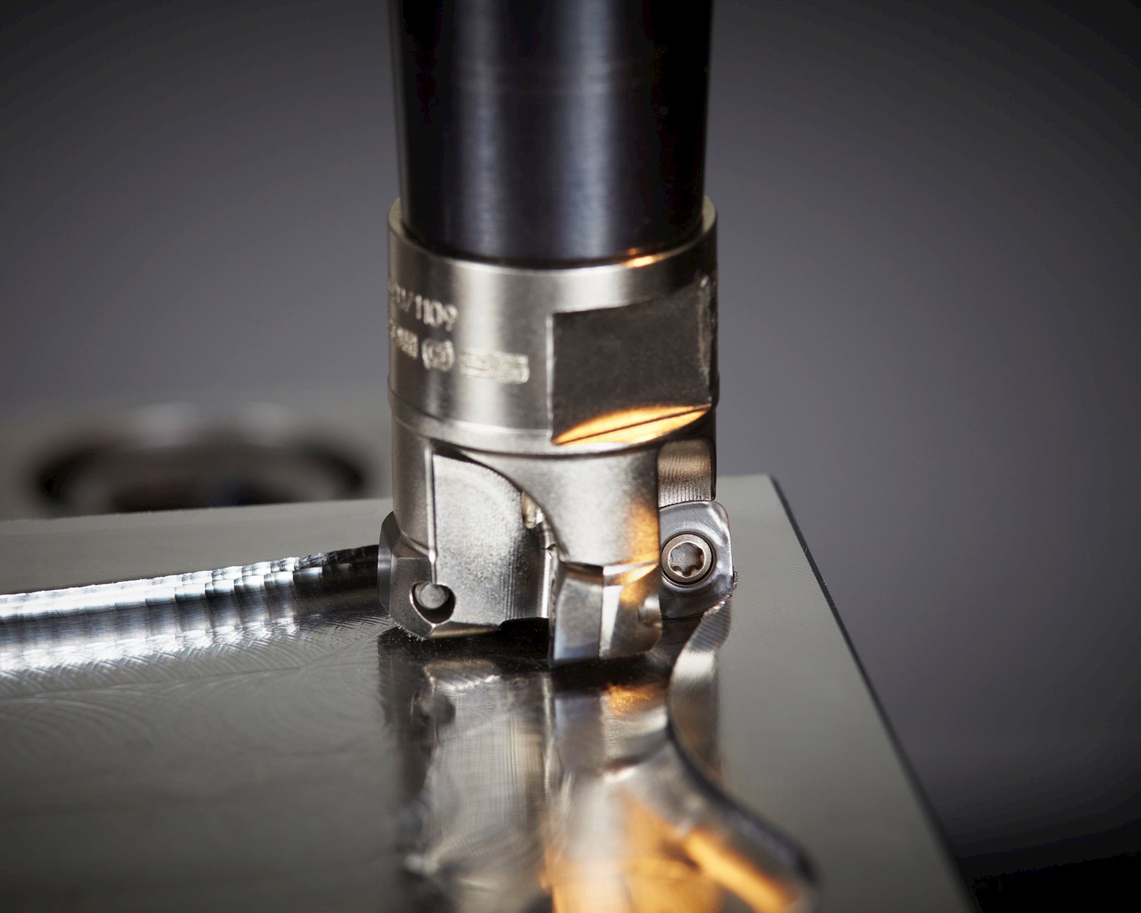
In milling operations, the radial depth of cut (Setp over) is another factor to consider. As the radial depth gets lower, the cutting speed can be increased. We can increase the speed since a smaller radial depth allows more time for each tooth to cool outside the material. The amount we can increase depends on the cutter's diameter and the ratio between it and the radial depth (Ae/d). You should assume that the starting point recommendation is for Ae/d=0.5 and use the table below to get the speed adjustment factor.
Feedrateformulafor milling
As the work advances into the cutter, each tooth of the cutter advances into the work an equal amount producing chips of equal thickness.
The overall stability of the setup largely determines the appropriate speed for a machining application, which is a personal assessment.
Feed per toothunit
Cutting speed is defined as the speed at the outside edge of the tool as it is cutting. This is also known as surface speed. Surface speed, surface footage, and surface area are all directly related. If two tools of different sizes are turning at the same revolutions per minute (RPM), the larger tool has a greater surface speed. Surface speed is measured in surface feet per minute (SFM). All cutting tools work on the surface footage principle. Cutting speeds depend primarily on the kind of material you are cutting and the kind of cutting tool you are using. The hardness of the work material has a great deal to do with the recommended cutting speed. The harder the work material, the slower the cutting speed. The softer the work material, the faster the recommended cutting speed (See Figure 1).
Supplier catalogs list multiple subgroups within each material group. Although this may be confusing, it is not the place to take shortcuts! Invest adequate time in classifying your material before proceeding to the next step.
Feedrateformulafor turning
Feeds for end mills used in vertical milling machines range from .001 to .002 in. feed per tooth for very small diameter cutters on steel work material to .010 in. feed per tooth for large cutters in aluminum workpieces. Since the cutting speed for mild steel is 90, the RPM for a 3/8” high-speed, two flute end mill is

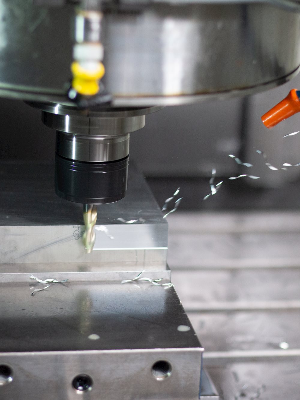
Drilling machines that have power feeds are designed to advance the drill a given amount for each revolution of the spindle. If we set the machine to feed at .006” the machine will feed .006” for every revolution of the spindle. This is expressed as (IPR) inches per revolution
To fine-tune the speed, refer to the chart that displays the hardness difference between the material you're working on and the material for which you have the original data. The Y-axis shows the percentage of adjustment needed for the cutting speed.
The range of cutting speeds that can be used is quite wide, and there are no definitive rules regarding the best option. Choosing a higher cutting speed will boost productivity but will result in a shorter lifespan for the tool. Conversely, selecting a lower cutting speed will lengthen the lifespan of the tool but will decrease productivity. The best decision will depend on your objectives and personal preferences.
In many cases, you may have personal knowledge or catalog recommendations for the cutting speed of a material in its annealed state, but it may require heat treatment before machining.
Erez Speiser is the founder and developer of the Machining Doctor Website. The platform encompasses his 30 years of experience in the machining industry, during which he held managerial positions in Engineering, Production, and Marketing. Combining his extensive knowledge of the industry and web development skills, Erez founded the Machining Doctor - a platform that serves as a hub for industry professionals to access his wealth of expertise and insights. Contact him on LinkedIn.
This article has been created in collaboration with Machining Doctor and Seco Tools. Cutting tool suppliers provide recommendations for cutting speed, but these are broad and intended for perfect conditions. These recommendations are too high in many cases, and we need to adjust them for our specific application. We can use speeds and feeds calculators or the Seco Assistant. However, understanding the parameters influencing calculations will enable better decision-making, longer tool life, and higher productivity. Identify your material correctlySupplier catalogs list multiple subgroups within each material group. Although this may be confusing, it is not the place to take shortcuts! Invest adequate time in classifying your material before proceeding to the next step. Discover the material groups in details Hardness Matters In many cases, you may have personal knowledge or catalog recommendations for the cutting speed of a material in its annealed state, but it may require heat treatment before machining.PH stainless steels or high alloy steels are common examples of this scenario. Raw material hardness affects cutting speed adjustment.To fine-tune the speed, refer to the chart that displays the hardness difference between the material you're working on and the material for which you have the original data. The Y-axis shows the percentage of adjustment needed for the cutting speed. Stability The overall stability of the setup largely determines the appropriate speed for a machining application, which is a personal assessment.It depends on the quality of both the workpiece and the cutting tool's clamping, as well as the overhang of the tool.To assess stability, rate it on a scale of 0 to 10, where 10 represents a perfectly stable setup with a short tool overhang, and 0 represents a poor setup. Adjust the speed according to the factors from the chart provided (assuming that the catalog recommendation refers to a score of 8). Tool life or productivity?The range of cutting speeds that can be used is quite wide, and there are no definitive rules regarding the best option. Choosing a higher cutting speed will boost productivity but will result in a shorter lifespan for the tool. Conversely, selecting a lower cutting speed will lengthen the lifespan of the tool but will decrease productivity. The best decision will depend on your objectives and personal preferences. Stepp-Over in Milling (Ae)In milling operations, the radial depth of cut (Setp over) is another factor to consider. As the radial depth gets lower, the cutting speed can be increased. We can increase the speed since a smaller radial depth allows more time for each tooth to cool outside the material. The amount we can increase depends on the cutter's diameter and the ratio between it and the radial depth (Ae/d). You should assume that the starting point recommendation is for Ae/d=0.5 and use the table below to get the speed adjustment factor. It is important to remember that the information presented here is not purely scientific. Nonetheless, it can be a useful guide for adjusting cutting speeds based on application conditions. Erez Speiser is the founder and developer of the Machining Doctor Website. The platform encompasses his 30 years of experience in the machining industry, during which he held managerial positions in Engineering, Production, and Marketing. Combining his extensive knowledge of the industry and web development skills, Erez founded the Machining Doctor - a platform that serves as a hub for industry professionals to access his wealth of expertise and insights. Contact him on LinkedIn. Inline Content - SurveyCurrent code - 5fce8e61489f3034e74adc64
Tap guides are an integral part in making a usable and straight thread. When using the lathe or the mill, the tap is already straight and centered. When manually aligning a tap, be careful, as a 90° tap guide is much more accurate than the human eye.


 0086-813-8127573