
Carbide Insert Threading Tools and Helix Angle for Manual ... - threading insert angle
Choosing the right insert shape for your turning tool is essential. The shape of the insert can affect the vibration during operation, the ability to turn complex contours, the strength of the insert and its ability to take bigger and heavier cuts.
G6 tolerancecalculator
ISO and ANSI both group fits into three categories: clearance, location or transition, and interference. Within each category are several codes to define the size limits of the hole or shaft – the combination of which determines the type of fit. A fit is usually selected at the design stage according to whether the mating parts need to be accurately located, free to slide or rotate, separated easily, or resist separation. Cost is also a major factor in selecting a fit, as more accurate fits will be more expensive to produce, and tighter fits will be more expensive to assemble.
Solid Carbide Drills Feeds and Speeds. Material. BRINELL. HARDNES. S (BHN) ... FEED PER REVOLUTION BY DRILL DIAMETER (IPR). 1/16". 1/8". 1/4". 1/2". 3/4"+.
Each member brings with them their own experience and know-how to add to our growing pool of technical knowledge. That’s why our services are known for being the best in the business!
Methods of producing work to the required tolerances to achieve a desired fit range from casting, forging and drilling for the widest tolerances through broaching, reaming, milling and turning to lapping and honing at the tightest tolerances.[1]
Some of the below chipbreakers are available on both negative and positive inserts but the min-max depths of cut may vary.
The smaller RC numbers have smaller clearances for tighter fits, the larger numbers have larger clearances for looser fits.[4]
G6 ToleranceChart
The chip breaker is represented as 2 letters in the ISO code. The chip breaker affects the cutting resistance, if the cutting resistance is low, it can avoid chipping and fracturing of the cutting edges. Reduced cutting resistance can also decrease the tool load and heat built up. The chip breaker also determines the depth of cut the insert can take, if you are not applying the correct depth of cut then you won’t be activating the chip breaker, this can cause the swarf to build up and become stringy, some people refer to this as a bird’s nest.
G6 Tolerancechart pdf
Fits of this kind are intended for use where accuracy is not essential. It is suitable for great temperature variations. This fit is suitable to use without any special requirements for precise guiding of shafts into certain holes.
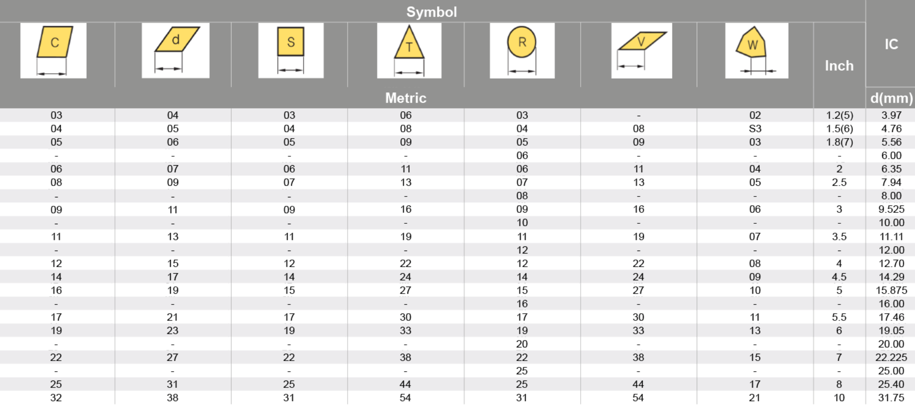
For insert shapes such as round, square, triangle & trigon, this would then indicate the diameter of the inscribed circle (IC).
A fit is either specified as shaft-basis or hole-basis, depending on which part has its size controlled to determine the fit. In a hole-basis system, the size of the hole remains constant and the diameter of the shaft is varied to determine the fit; conversely, in a shaft-basis system the size of shaft remains constant and the hole diameter is varied to determine the fit.
All turning inserts have a unique ISO code that contains various letters and numbers – believe it or not, these actually mean something! From just looking at the ISO code you can figure out the insert’s shape, relief angle, tolerance, cross-section type, cutting-edge length, thickness, radius, and chip breaker!
It is a 2-digit number that generally indicates the width or length, however this is only applicable to insert shapes with no IC (inscribed circle), such as rectangular and parallelograms.
Interference fits, also known as press fits or friction fits, are fastenings between two parts in which the inner component is larger than the outer component. Achieving an interference fit requires applying force during assembly. After the parts are joined, the mating surfaces will feel pressure due to friction, and deformation of the completed assembly will be observed.
They typically range from sizes 2 to 16 and the larger the number, the more bigger the screw. The #8 sized screw is the most commonly-used one. According to the ...
The cross-section highlights the differences in the design of the insert, such as the fixing holes, countersinks, and special features. This dictates what clamping method would be used to fix the insert on to the tool holder.
Running add-ins. To run add-ins, open up the scrips and add-ins dialog as before. Toggle over to the Add-Ins tab. You'll see a list of available ...
G6 tolerance in mmchart pdf
The thickness of a turning insert is measured from the bottom of the insert to the top of the cutting edge. This will be shown as a 2-digit number except where the insert features a T and then a single digit number eg T3. This is due to the fact that there are more than one increment within each mm. eg 03 is 3.18mm whereas T3 is thickest at 3.97mm.
The relief angle for a milling insert is of paramount importance in achieving efficient and successful machining operations.

Shrink fits serve the same purpose as force fits, but are achieved by heating one member to expand it while the other remains cool. The parts can then be easily put together with little applied force, but after cooling and contraction, the same dimensional interference exists as for a force fit. Like force fits, shrink fits range from FN 1 to FN 5.[3]
Mayo Performance Specialties ... Areas Served: Arlington Texas, Tarrant County, Ft Worth TX, Grapevine, Bedford, Euless,… Services: all car repair services ...
It plays a crucial role in chip formation, tool life, cutting forces, and surface finish. Understanding the influence of the relief angle and selecting the appropriate one can greatly enhance machining performance, productivity, and the quality of the finished product.
G6 tolerance in mmchart
The ISO system uses an alpha-numeric code to illustrate the tolerance ranges for the fit, with the upper-case representing the hole tolerance and lower-case representing the shaft. For example, in H7/h6 (a commonly-used fit) H7 represents the tolerance range of the hole and h6 represents the tolerance range of the shaft. These codes can be used by machinists or engineers to quickly identify the upper and lower size limits for either the hole or shaft. The potential range of clearance or interference can be found by subtracting the smallest shaft diameter from the largest hole, and largest shaft from the smallest hole.
H6Tolerance in mm
Factory name. Address. City. Zip code Province. Country. # of workers. Category. Jiangsu Asset Underwear Co., Ltd. No. 6, Wang One Road, ...
In this blog, we will discuss how to identify all these key dimensions, so you will never need to check for part numbers again.
Tolerance dimensions are indicated by a letter ranging from A - U. Dimension A relates to the inscribed circle (IC), dimension B relates to the insert height (for pentagon, triangle, and trigon shapes – for other polygons, the dimension B relates to the distance that is measured along the bisector of the corner angle) and dimension T relates to the thickness of the insert.
The International Organization for Standardization system splits the three main categories into several individual fits based on the allowable limits for hole and shaft size. Each fit is allocated a code, made up of a number and a letter, which is used on engineering drawings in place of upper & lower size limits to reduce clutter in detailed areas.
Their tensile modulus range from 230 Gpa for PAN based High Strength fibers, up to 900 GPa for Ultra High Modulus fibers made from coal tar pitch! Carbon fiber ...
G6 Tolerancefor Shaft
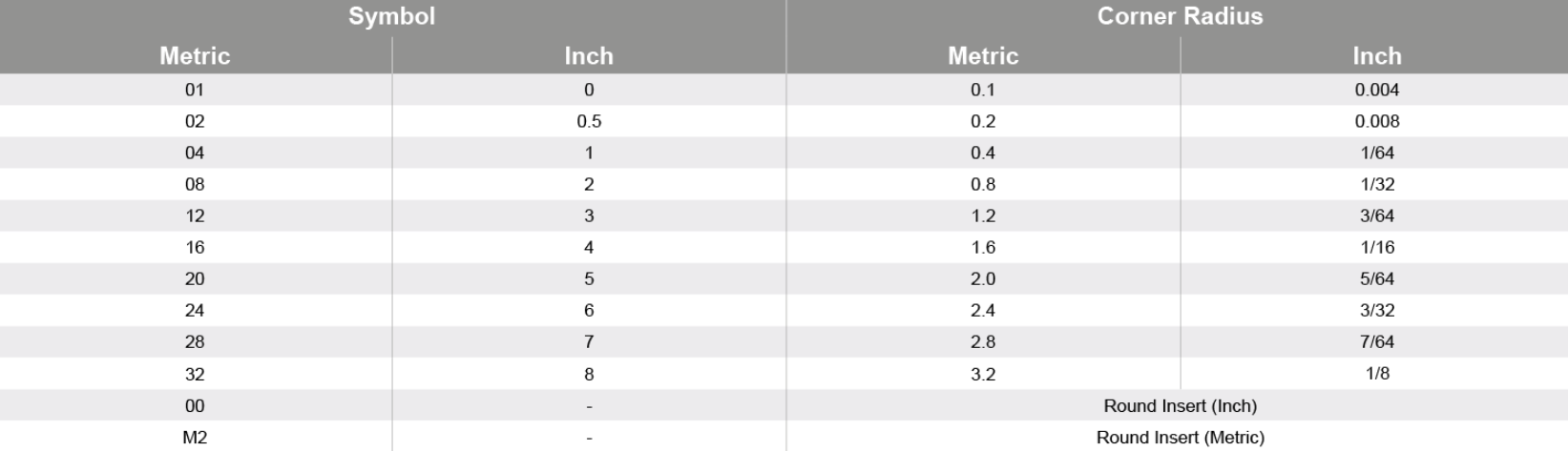
The nose radius of an insert can affect the performance. A larger nose radius can result in the use of higher feed rates, and larger depths of cut, and they can handle more pressure, making them much better for heavier metal removal. Whereas a turning insert with a smaller nose radius can only take smaller depths of cut, they also have weaker cutting edges, and they can only handle a small amount of vibration but are much better for finishing as they are sharper and have less surface contact.
Engineering fits are generally used as part of geometric dimensioning and tolerancing when a part or assembly is designed. In engineering terms, the "fit" is the clearance between two mating parts, and the size of this clearance determines whether the parts can, at one end of the spectrum, move or rotate independently from each other or, at the other end, are temporarily or permanently joined. Engineering fits are generally described as a "shaft and hole" pairing, but are not necessarily limited to just round components. ISO is the internationally accepted standard for defining engineering fits, but ANSI is often still used in North America.
Fits of this kind are intended for the accurate location but with greater maximum clearance than class RC1. Parts made to this fit turn and move easily. This type is not designed for free run. Sliding fits in larger sizes may seize with small temperature changes due to little allowance for thermal expansion or contraction.
Fits of this kind are designed for machines running at higher running speeds, considerable bearing pressures, and heavy journal pressure. Fits of this kind also can be described with greater clearances with common requirements for fit precision.
1/2" Minimum Bore, 3/8" Diameter x 3" Long Carbide Shank RH Boring Bar For CCGT 21.5_ Inserts. INTERNAL TOOL. 161699. 161699. 16-1699. 0.3750"Diameter.
Fits of this kind are mostly for running fits on accurate machinery with moderate surface speed, bearing pressures, and journal pressures where accurate location and minimum play are desired. Fits of this kind also can be described as smaller clearances with higher requirements for precision fit.
H7tolerance in mm
Force fits are designed to maintain a controlled pressure between mating parts, and are used where forces or torques are being transmitted through the joining point. Like interference fits, force fits are achieved by applying a force during component assembly.[3]
Workshops for Warriors is the only accredited 501(c)3 nonprofit organization in the United States that provides Veterans and Wounded Warriors training, ...
Fits of this kind are intended for use where wide commercial tolerances may be required on the shaft. With these fits, the parts with great clearances with having great tolerances. Loose running fits may be exposed to effects of corrosion, contamination by dust, and thermal or mechanical deformations.
All in all, this could be a real time saver if you have to cut a lot of all-thread, especially trimming pencil rods for hanging equipment, negating the need to ...
Check live running status of train 22140 Humsafar Express on RailYatri. It departs from NAGPUR | NGP at 19 H 40M. Download app to get your live train ...
Fits of this kind are about the closest fits which can be expected to run freely. Precision fits are intended for precision work at low speed, low bearing pressures, and light journal pressures. RC3 is not suitable where noticeable temperature differences occur.


 0086-813-8127573