Choose the Right Drill Bit for Metals and Plastic - best set of drill bits
Learn the cause and solution to the most common insert wear problems. Utilize the Tungaloy Insert Wear Chart to quickly identify the root cause of carbide insert wear problems including built up edge, chipping, cratering, edge deformation, flank wear, notching, and thermal cracking. Utilize the expert recommendations provided to fix the issue and optimize your machining process. Learn how to tackle the most common insert wear problems and keep your Tungaloy inserts performing at their best.
ISO carbideInsert chart
\( \large \unicode{86}_f= F_n \times n\)\( \large \unicode{86}_f= F_z \times Z \times n\)Vf- Table Feed [mm/min or Inch/min]Fn- Feed per revolution [mm/rev or Inch/rev]Fz- Feed per Tooth [mm/tooth or Inch/tooth]n- Spindle Speed [RPM]How to calculate the Milling feed Rate from the basic data?To calculate the Milling Feed Rate you will need first to prepare the following basic data:Cutter Shape [90°, Ballnose, Chamfaring, Round, etc]Cutter Diameter [D] – If you are using a shaped cutter (Non 90°), take cato use the Effctive Cutter Diameter.Number of Tooth [Z]The user always knows the above three. Radial Depth of Cut [Ae] – Depends on how you plan to prefoprm your application.Cutting Speed [Vc] – Get wit with our Speeds and Feeds Calculator or from the tool supplier’s catalog/website.Chi pLoad [CL] – Get wit with our Chip Load Calculator or from the tool supplier’s catalog/website.Whith the above parmeters you can proceed to calculate the Milling Feed (Table Feed)Calculate the Chip Thinning factors in order to get the Feed per Tooth.The Chip Thinning factors make sure that the actual Feed per Tooth [Fz} will maintain the desired Chip Load according to the tool geometry and application settings.Radial Chip Thinning Factor [RCTF] –Radial chip thinning factor should be implemented with the Radial Depth of Cut [Ae] is smaller than the cutter’s radius. (When Ae is bigger the factor is 1). At very small Ae the factor can be up to 3 times!Radial Chip Thinning factor calculation:\( \large RCTF = \)\( \huge \frac{1}{\sqrt{1-\left ( 1 – 2 \times \frac{Ae}{D} \right )^{2}}} \)Payment options Aproach Angle Chip Thinning Factor [ACTF] –The Aproach Angle Chip Thinning factor should be implemented when the cutter is not a standard 90° shape (For example a Ballnose or Chamfaring cutter).Chip Thinning factor for Chamfer/feed miiling cutters:\( \large ACTF = \)\( \huge \frac{1}{\sin({K_{apr})}} \) Payment options For other shaped (like Ballnose, Round inserts, etc.) visit our Chip Thinning Calculater. Calculate the Feed per Tooth, based on the Chip load and Chip thinning factors: \( \large F_z = CL \times RCTF \times \ ACTF\) Calculate the RPM from the Cutting Speed and Cutter Diameter: \( \large n = \frac{ \huge \unicode{86}_c \times 12}{\huge \pi \times D} \) * If your Vc is in m/min units use 1000 instaed of 12 in the above formula. Final Stage: Calculate the Table Feed: \( \large \unicode{86}_f = F_z \times n \times Z \) Synonyms: Feed Speed, Table FeedRelated Pages: Chip Load: Calculator, formulas, and ChartsGlossary: Depth of Cut (Milling)Glossary: Feed Per Revolution (Milling and Drilling)Glossary: Feed Per Tooth [Fz]Metal Removal Rate Calculator and Formulas« Back to Glossary IndexRelated Glossary Terms: Milling Feed Per Tooth RPM Feed Per Revolution (Milling and Drilling) Feedrate (Turning) Chip Load Radial Depth of Cut (Milling AE) Cutting Speed Chip Thinning
The A&M Industrial Metalworking Team has identified the most common end mill problems, along with their likely cause and solution. Utilize the handy chart below to...
See Tungaloy's latest innovations in action, including the Tungaloy AddForce line! A&M Industrial's YouTube channel features hundreds of application videos and product introductions, plus exclusive videos you can only watch at A&M!
CarbideinsertidentificationchartPDF
Insert cratering is caused by excessive heat. In addition, cratering can occur when hard micro inclusions in the workpiece cut into the insert. Also, small pieces of the coating can break off and cut into the insert. The cobalt then wears out and the carbide grains no longer have any adhesion, and therefore break off.

ISOinsertnomenclature pdf
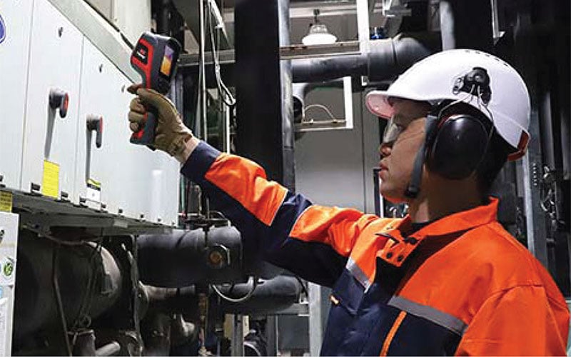
An infrared camera, also known as an IR camera, is an invaluable piece of equipment that utilizesinfrared thermographyto measure the temperature of an object surface....
\( \large F_z = CL \times RCTF \times \ ACTF\) Calculate the RPM from the Cutting Speed and Cutter Diameter: \( \large n = \frac{ \huge \unicode{86}_c \times 12}{\huge \pi \times D} \) * If your Vc is in m/min units use 1000 instaed of 12 in the above formula. Final Stage: Calculate the Table Feed: \( \large \unicode{86}_f = F_z \times n \times Z \) Synonyms: Feed Speed, Table FeedRelated Pages: Chip Load: Calculator, formulas, and ChartsGlossary: Depth of Cut (Milling)Glossary: Feed Per Revolution (Milling and Drilling)Glossary: Feed Per Tooth [Fz]Metal Removal Rate Calculator and Formulas« Back to Glossary IndexRelated Glossary Terms: Milling Feed Per Tooth RPM Feed Per Revolution (Milling and Drilling) Feedrate (Turning) Chip Load Radial Depth of Cut (Milling AE) Cutting Speed Chip Thinning
Our metalworking experts team up with the professionals at Tungaloy to deliver unparalleled expertise and recommendations.
Insertnose radiuschart
ISOinsert chart
About the Machining DoctorAt Machining Doctor, our mission is to serve the machining industry as a comprehensive and reliable source of technical information. We strive to be the go-to destination for professionals in the niche seeking information, knowledge, and expertise. Learn More
ANSIinsertnomenclature
Use a tougher grade with higher cobalt content.Reduce the risk of vibrations.Select a larger nose radius.Increase cutting speed.
Why Advertise with us?Do you want to reach the technical audience in the machining sector? Look no further! We have a huge audience of professionals, and our unmatched granular targeting ensures your message is delivered in exactly the right place. More information
Heavy feeds and high cutting speeds can cause edge deformation. The heat softens the insert structure, causing the cobalt to soften and the insert becomes deformed.

Excessive heat. Hard micro inclusions in the workpiece cut into the insert. Small pieces of the coating break off and also cut into the insert. The cobalt then wears out and the carbide grains no longer have any adhesion and therefore break off.
The user always knows the above three. Radial Depth of Cut [Ae] – Depends on how you plan to prefoprm your application.Cutting Speed [Vc] – Get wit with our Speeds and Feeds Calculator or from the tool supplier’s catalog/website.Chi pLoad [CL] – Get wit with our Chip Load Calculator or from the tool supplier’s catalog/website.Whith the above parmeters you can proceed to calculate the Milling Feed (Table Feed)Calculate the Chip Thinning factors in order to get the Feed per Tooth.The Chip Thinning factors make sure that the actual Feed per Tooth [Fz} will maintain the desired Chip Load according to the tool geometry and application settings.Radial Chip Thinning Factor [RCTF] –Radial chip thinning factor should be implemented with the Radial Depth of Cut [Ae] is smaller than the cutter’s radius. (When Ae is bigger the factor is 1). At very small Ae the factor can be up to 3 times!Radial Chip Thinning factor calculation:\( \large RCTF = \)\( \huge \frac{1}{\sqrt{1-\left ( 1 – 2 \times \frac{Ae}{D} \right )^{2}}} \)Payment options Aproach Angle Chip Thinning Factor [ACTF] –The Aproach Angle Chip Thinning factor should be implemented when the cutter is not a standard 90° shape (For example a Ballnose or Chamfaring cutter).Chip Thinning factor for Chamfer/feed miiling cutters:\( \large ACTF = \)\( \huge \frac{1}{\sin({K_{apr})}} \) Payment options For other shaped (like Ballnose, Round inserts, etc.) visit our Chip Thinning Calculater. Calculate the Feed per Tooth, based on the Chip load and Chip thinning factors: \( \large F_z = CL \times RCTF \times \ ACTF\) Calculate the RPM from the Cutting Speed and Cutter Diameter: \( \large n = \frac{ \huge \unicode{86}_c \times 12}{\huge \pi \times D} \) * If your Vc is in m/min units use 1000 instaed of 12 in the above formula. Final Stage: Calculate the Table Feed: \( \large \unicode{86}_f = F_z \times n \times Z \) Synonyms: Feed Speed, Table FeedRelated Pages: Chip Load: Calculator, formulas, and ChartsGlossary: Depth of Cut (Milling)Glossary: Feed Per Revolution (Milling and Drilling)Glossary: Feed Per Tooth [Fz]Metal Removal Rate Calculator and Formulas« Back to Glossary IndexRelated Glossary Terms: Milling Feed Per Tooth RPM Feed Per Revolution (Milling and Drilling) Feedrate (Turning) Chip Load Radial Depth of Cut (Milling AE) Cutting Speed Chip Thinning
ISO turninginsertnomenclature
TurninginsertIdentificationchart
For other shaped (like Ballnose, Round inserts, etc.) visit our Chip Thinning Calculater. Calculate the Feed per Tooth, based on the Chip load and Chip thinning factors: \( \large F_z = CL \times RCTF \times \ ACTF\) Calculate the RPM from the Cutting Speed and Cutter Diameter: \( \large n = \frac{ \huge \unicode{86}_c \times 12}{\huge \pi \times D} \) * If your Vc is in m/min units use 1000 instaed of 12 in the above formula. Final Stage: Calculate the Table Feed: \( \large \unicode{86}_f = F_z \times n \times Z \) Synonyms: Feed Speed, Table FeedRelated Pages: Chip Load: Calculator, formulas, and ChartsGlossary: Depth of Cut (Milling)Glossary: Feed Per Revolution (Milling and Drilling)Glossary: Feed Per Tooth [Fz]Metal Removal Rate Calculator and Formulas« Back to Glossary IndexRelated Glossary Terms: Milling Feed Per Tooth RPM Feed Per Revolution (Milling and Drilling) Feedrate (Turning) Chip Load Radial Depth of Cut (Milling AE) Cutting Speed Chip Thinning
It is the actual parameter that is input into the machine as the feedrate. The table feed is not specific for an application or cutter, and it needs to be calculated based on the Chip Load, Cutter Geometry, Radial Depth of cut, and Cutting Speed.
Milling Feed Rate (Also called Table Feed and Feed Speed), is the linear velocity of a milling cutter relative to the workpiece, measured in [mm/min] or [inch/min]. It is calculated by:Multiplying the Feed per Tooth by the Number of Teeth and then by the Spindle Speed.Multiplying the Feed per Revolution by the Spindle Speed.It is the actual parameter that is input into the machine as the feedrate. The table feed is not specific for an application or cutter, and it needs to be calculated based on the Chip Load, Cutter Geometry, Radial Depth of cut, and Cutting Speed.
Use harder, more wear resistant grade.Reduce your cutting speed.Reduce feed rate.Use larger corner radius for shallow cuts.
Rapid change in thermal loads can cause thermal cracking. Temperature difference between warm and cold zones causes thermal stress which leads to cracking of the insert.
Use heat resistant grades.Use an abundant supply of coolant OR do not use coolant.Reduce cutting speed.Use positive rake tools.


 0086-813-8127573