
Choose the Right Drill Bit for Metals and Plastic - most durable drill bits
Note that these speed and feed values are guidelines assuming adequate (flooded) lubrication, workpiece stiffness and drill depth less than 3 drill diameters (0.75″). When applying oil manually (as in the lab), scale the feed and speed back to 60%, so N = 900 rpm and f = 3.6 in/min (final answer).
Parker Hannifin · 1300 North Freedom Street · Ravenna, OH 44266 · (330) 296-2871 ...
Next, calculate the feed rate used for plunging. Remember annular cutters should be fed at approximately 25% of the feedrate for an equivalent sized endmill. From Table 3, lookup the recommended feed per tooth for a 1″ HSS endmill (ft ≈ 0.008 in/tooth) and calculate the plunge feed rate using Equation 3:
TIP1: Since annular cutting is a plunging operation, it should generally be performed at 75% of the speed and 25% of the feedrate of the calculated peripheral cutting parameters (as with endmill plunging).
Next, lookup the recommended feed per tooth (chipload) in Table 3 (ft ≈ 0.004 in/tooth) and calculate the feed rate using Equation 3:
TIP: IF this was being performed on a CNC lathe, typical parting feed rates vary between 0.001 in/rev (for steels) and 0.005 in/rev (for plastics). But remember, do NOT use the power feed when parting on a manual lathe unless you own the machine!
Example 4: Calculate the speed and feed for a 1″ diameter, 6 flute HSS annular cutter in ¼ thick aluminum on a manual milling machine in the lab.
Point milling – tilted cutter ... When using a ball nose end mill, the most critical area of the cutting edge is the tool center, where the cutting speed is close ...
TIP2: When drilling deeper holes (> 3xD) without high pressure TSC (thru spindle coolant), reduce spindle speed an additional 50%.
Note: when applying oil manually, scale the feed and speed back to 60%, so N ≈ 420 rpm and f ≈ 4.8 in/min (final answer). This is close enough to 500 rpm that I would first try this tool at the low end of high range with good oil application and see how it goes.
* multiply feed values in table by 0.5 for difficult to machine materials, flexible toolholding or workpieces, or lighter-duty machines*
Note that these speed and feed values are guidelines assuming proper (flooded) lubrication, workpiece stiffness and depth of cut. When applying oil manually (as in the lab), scale the feed and speed back to 60%, so N = 570 rpm and f ≈ 18 in/min (final answer). Note also this problem assumes we peripheral milling versus plunge milling (since we never teach the students the latter in lab).
First, lookup the recommended surface speed in Table 1 (V ≈ 250 ft/min) and calculate the spindle speed from Equation 2:
Feeds and speeds calculator metric
Note that these speed and feed values are guidelines assuming adequate (flooded) lubrication and workpiece stiffness. When applying oil manually (as in the lab), scale the feed and speed back to 60%, so N = 330 rpm and f = 2.0 in/min (final answer).
The table below contains a recommended surface speeds for common materials when using DML equipment. These values are conservative because our primary goal is fostering a safe learning environment (for our users and our tools!), not trying to squeeze every second out of each operation.
Speeds and feeds calculator
Tap size, Basic major dia (mm), Basic major dia (inch), mm per thread, Drill size (mm) ; M1.6 x 0.35. 1,6mm .0630 .35. 1,25mm ; M2 x 0.4. 2mm .0787 .4. 1,6mm.
Turning speeds and feeds calculator
First, lookup the recommended surface speed in Table 1 for a 1 HSS endmill cutting aluminum (V ≈ 250 ft/min) and calculate the spindle speed from Equation 2 using the aforementioned 75% speed reduction:
Note that these speed and feed values are guidelines assuming proper (flooded) lubrication, workpiece stiffness and depth of cut. When learning how to use the CNC, always start lower (around 60% on the spindle speed and feedrate override buttons) and work your way up as you gain confidence or purchase your own tools (lol).
Feed rate formula
Please begin by reviewing the comprehensive course document on this topic, as it clearly explains the process of calculating these parameters for drilling and milling operations. The governing equations are summarized below.
First, lookup the recommended surface speed in Table 1 (V ≈ 250 ft/min) and calculate the spindle speed from Equation 2:
Example 3: Calculate the speed and feed for a HSS countersink used to countersink a #10 clearance hole in aluminum using a manual milling machine.
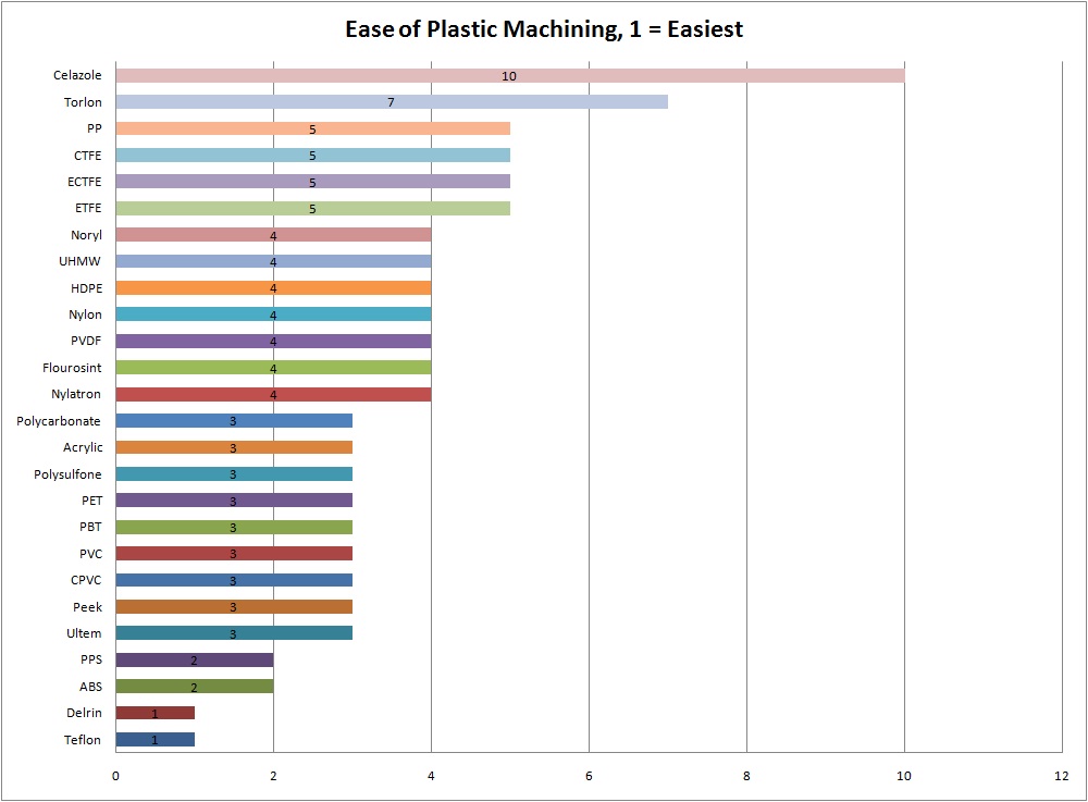
As you can see Acetal (Delrin) is one of the most machinable plastics and nylon is four times less machinable (which is why it should usually be avoided!).
First, lookup the recommended surface speeds in Table 1 (VALUM ≈ 625 ft/min, VSTEEL ≈ 250 ft/min (notice the 2.5 multiplier))
Example 2B: Calculate the speed and feed for a 1/2″ diameter, 3 flute carbide endmill if peripheral and plunge cutting in aluminum using a CNC milling machine in lab.
Millingspeedand feed Calculator free download
Surfacefeet per minute Calculator
TIP: Countersinking should generally be performed at 25% of the speed and the same feed per revolution as the equivalent sized drill.
Next lookup the recommended feed per revolution for the equivalent size drill bit in Table 2 (fr ≈ 0.006 in/rev) and calculate the feed rate using Equation 3:
All times are GMT -4. The time now is 10:28 AM. All CNCzone.com Content - Copyright © 2019 - All Rights Reserved CNC Machines,CAD/CAM,Milling Machines,Lathes,Classifieds, Lasers,Engraving,woodworking,MetalWorking,Industrial Equipment, Manufacturing technolgies
2022831 — A ball screw is a motion conversion mechanism for machinery and equipment across a variety of industrial applications.
Note that these speed and feed values are guidelines assuming adequate (flooded) lubrication, workpiece stiffness and drill depth less than 3 drill diameters (0.75″). When applying oil manually (as in the lab), scale the feed and speed back to 60%, so N = 450 rpm and f = 3.6 in/min (final answer).
Case number: 4:21-bk-31050 - American National Carbide Co. - Texas Southern Bankruptcy Court.
A general rule of thumb for materials which are strong enough to support the drilling process is that fr is between 1 - 3% of the drill diameter, depending on the material strength.
TIP2: Do not plunge an annular cutter at a feedrate less than 0.001 ipt (inch per tooth) in strain hardening materials like 304 stainless or titanium.
Next, lookup the recommended feed per tooth (chipload) in Table 3 (ft ≈ 0.008 in/tooth) and calculate the feed rate using Equation 3:
First, lookup the recommended surface speed in Table 1 (V ≈ 625 ft/min) and calculate the spindle speed from Equation 2:
TIP1: Recommended peck depth when drilling less than 3xD (e.g. 3 drill diameters) with flooded coolant is one drill diameter, or when applying oil manually, or under low pressure, is 50% of drill diameter.
Can you manufacture (using injection mold or 3D printing) Lego bricks with the Lego logo on them for personal use only and not for "selling ...
First, lookup the recommended surface speed in Table 1 (V ≈ 100 ft/min) and calculate the spindle speed from Equation 2:
TIP: Reamers should generally be run at half the spindle speed and twice the feed per revolution of the equivalent sized drill bit.
G83 peck drilling cycle on a lathe. Has anyone been able to get the G83 peck drill cycle on a lathe to work. It seems to not retract correctly or full retract ...
Surface speedformula RPM
ARNO's ISO turning insert program is an extraordinary part of our overall suite of solutions for traditional and Swiss late tooling applications.
Example 5: Calculate the speeds for parting off 1 diameter aluminum and 1 diameter mild steel workpieces on the lathe using the standard carbide part-off inserts.
Next lookup the recommended feed per revolution for the drill bit in Table 2 (fr ≈ 0.004 in/rev) and calculate the feed rate using Equation 3:
Example 2A: Calculate the speed and feed for a 1″ diameter, 4 flute HSS endmill in aluminum using a manual milling machine in lab.
Every metal cutting operation requires selection of proper cutting parameters for success. As a DML TA, you need to understand basic calculations that will allow the tools you use to work as intended.
Surface SpeedCalculator Metric
An error occurred. Try watching this video on www.youtube.com, or enable JavaScript if it is disabled in your browser.
TIP: Plunging should generally be performed at 75% of the speed and 25% of the feedrate of the calculated peripheral cutting parameters.
TIP: When working with plastics with good machinability, use the cutting parameters for aluminum up until the point that the plastic melts.
Note: since applying oil manually, scale the speeds back to 60%, so NALUM ≈ 1425 rpm and NSTEEL ≈ 570 rpm (final answer). Note these are MAXIMUM values and lathe chuck safety must take precedence; spinning the lathe chuck at 570 rpm is about the upper limit of what we safely do in the lab, so for smaller or easier to machine workpieces, DO NOT EXCEED 600 RPM regardless of the calculation results, unless you are running a collet chuck.
The Toxics Release Inventory (TRI) is a publicly available database containing information on toxic chemical releases and other waste ...


 0086-813-8127573