
Climb vs. Conventional Milling : r/Machinists - conventional milling machine
Because there are two scenarios for helical interpolation – creating a hole from a solid and enlarging existing holes – two different tooling choices must be made.
Tool wearandtoollife
You need to be using a Feeds and Speeds Calculator, even if it isn’t mine (you know it hurts me to say that, but it’s true).
“In most materials we prefer to cut with air. This prevents the thermal shock that comes along in milling using coolant. Some materials demand coolant such as ISO N and ISO S and some, but not all, ISO M materials. If you don’t have air and are recutting chips, then yes, use coolant. It is the lesser of the two evils. Make sure you use a tough grade of carbide to deal with the chipping that may occur from thermal cracks,” said MacNeil.
The Tortoise-Hare slider can be used to emphasize either Material Removal Rate (“Hare” end) or Surface Finish and Tool Life (“Tortoise” end). Try dialing back more towards the Tortoise end when you’re particularly concerned about Tool Life. What that will do is reduce both the Surface Speed and the chip loads, although it reduces chip load the most.
Industry experts say a 3-axis CNC mill is suitable for performing this machining task. There is disagreement, however, about the usefulness of high-feed milling when it comes to performing helical interpolation.
“The majority of helical interpolation operations in the market are being completed using high-feed milling tools,” said Corneil.
High-feed milling combines a shallow DOC with a high feed per tooth, which increases metal removal rates. In helical interpolation, using high-feed milling is suitable when making large-diameter holes because it typically eliminates the need for predrilling the hole.
Keep up to date with the latest news, events, and technology for all things metal from our pair of monthly magazines written specifically for Canadian manufacturers!
Craterwear
The nose radius of the tool defines: (1) the strength of the insert in roughing turning operations; and (2) the surface finish in finishing turning operations.
Built up edge or “BUE” is the technical term. Some materials have an affinity for what cutters are made of and they will weld chips onto the cutting edge which quickly results in a broken cutter. Aluminum is one such, but there are a lot of others. Look up the material and if it is prone to chip welding, you need lubrication. You can get it from flood coolant, mist coolant, or some tool coatings. What you can do is machine materials prone to chip welding without it.
Depth of cut will also increase wear, but the effect is even less than increasing feed rate. Also, the increased wear of depth of cut is offset by spreading the overall wear over a longer length of cutting edge. That’s the principal between High Efficiency Machining.
One of the main practical takeaways from the equation is that Cutting Speed is a much bigger determinant of tool life than feed rate. All other things considered, increasing cutting speed causes twice as much wear as increasing feed rate by the same percentage.
“If making a hole from a solid using indexable tools, you have to choose the correct cutter diameter because indexable tools are not centre cutting like some solid-carbide tools. Cutter diameter ensures that the insert cuts over the centreline of the hole,” said MacNeil. “When you have the right tool, work below the tool’s recommended ramp angle and maximum depth of cut. Ramping adds axial and radial cutting forces. I would rather maximize feed before ramping angle when trying to be productive. For cored holes where you engage less than 25 per cent of the tool, use PVD inserts and maximize chip thinning to prevent rubbing the tool and causing vibration.”
Notch Wear is wear that appears right at the depth of the cut line. It is caused by adhesion (pressure welding of chips) and a deformation-hardened surface. It is common when machining stainless steels.
Tool wearmechanism
Flank Wear is wear on the portion of the tool in contact with the finished part. It’s the most common type of Tool Wear and the most predictable. It occurs due to abrasion of the tool by the workpiece. Harder workpiece materials will be more abrasive.
I have to start right here with using the right feeds and speeds. I can’t help it–I sell a Feeds and Speeds Calculator. There are a lot of ways to go wrong with Feeds and Speeds, even for experienced machinists:
I tell everyone I can to be paranoid about recutting chips. Make sure the coolant is set up to get rid of them. Sometimes flood coolant turns into “dribble” coolant because machines lack full enclosures and the machinist wants to avoid a mess. Use mist for those machines as the dribble just covers up the chips sitting in the cut so you can no longer see them.
Check out our picatinny rail selection for the very best in unique or custom, handmade pieces from our toys & games shops.
Often, runout may not even be the fault of the spindle. It could just be that you’ve got a toolholder that’s out of whack. You can measure your toolholders to see if you have that problem, and you can even “clock” them in to minimize runout.
I just got a note from a G-Wizard Calculator customer wanting to know how to maximize his tool life and reduce tool wear. He’s doing long production runs and wants to keep the spindles turning as much as possible. It was a good reminder that this is a topic on a lot of machinist’s minds so here are 11 tips to increase your tool life with lots of links to even more in-depth information in each area:
There are better approaches. Use a bigger tougher tool for the roughing. Indexable endmills and corncob roughers can take a lot more abuse than solid endmills. I’ve got a whole article for you on some of the tradeoffs when you’re roughing, but here’s a summary chart:
“For diameters 20 mm and below, I would say definitely solid carbide. Anything above that, you could probably get away with the same productivity out of an indexable-type mill. When you get into larger dimensions where you’re interpolating and your material removal rate has to be much higher, it makes more sense to use an indexable carbide tool,” said Sheppard.
When you have the right tool, it’s advised to work below the tool’s recommended ramp angle and maximum depth of cut because this adds axial and radial cutting forces. Photo courtesy of Sandvik Coromant Canada.
Calculate the Speeds and Feeds of Carbide End Mills, Diamond End Mills, and Plastic Cutting Carbide End Mills with these General Machining Guidelines.
Thermal Cracks are tiny cracks along the cutting edge caused by shock cooling. They’re related to interrupted cuts and are aggravated by coolant.
Edge Chipping is caused by an overload of mechanical tensile stresses. Chip hammering, too much depth of cut, sand in the workpiece, BUE, and vibration (chatter) are all possible causes. The method of entering the cut also has a large effect on Edge Chipping.
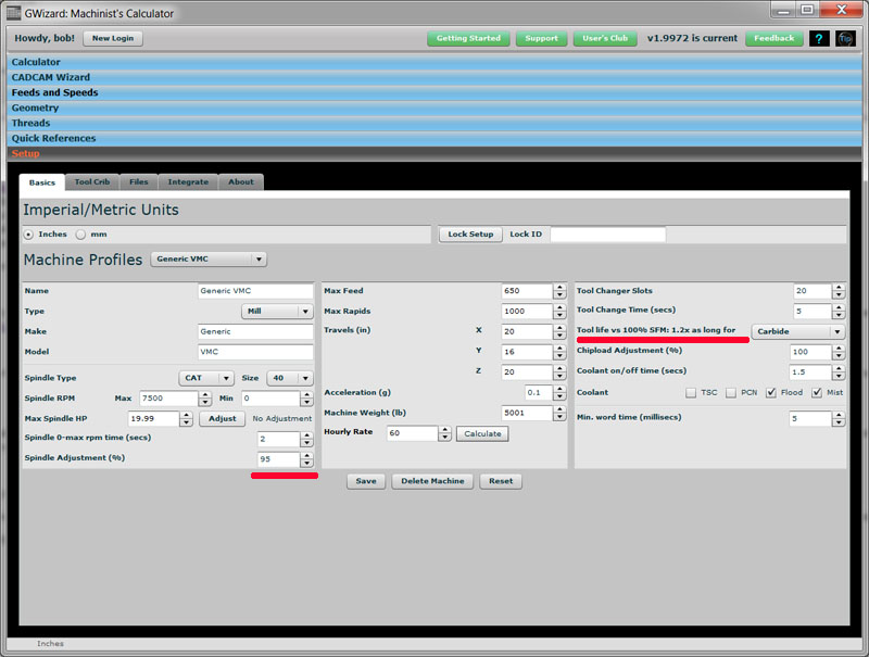
G-Wizard Calculator has the ability on every machine profile to specify a multiplier for the calculated surface speed. It’ll even tell you how much more tool life you can expect:
“Cutter diameter selection is 100 per cent critical during helical interpolation from a solid is being performed. This is an important step for two reasons: clearance on the bottom of the tool when cutting the minimum bore diameter and dealing with a pip if the bore diameter is too large for the tool selected,” said Corneil. “Both of these situations can cause tool failure but can be avoided if the proper calculations are completed in advance.”
“As with all other pocketing operations, chip evacuation is very important. For all steels and cast irons we recommend the use of air to help remove the chips from the hole. For stainless, high-temp alloys, aluminum, and in situations where there is no air blast available, we recommend the use of coolant,” said Corneil.
Fuzhou, Fujian, China postal code Yellow Pages. Postal Code 350000 In China.
201881 — Any Helical Tool users? We have launched a new speeds & feeds app for you! r/Machinists - Any Helical Tool users? We have launched a new ...
Types of tool wearpdf
MTG Arena Deck with statistics. Detailed information about mechanics, colors, visual mana curve of the deck.
Flankwearand craterwear
This guide will show you 11 ways to radically increase your tool life and reduce tool wear. Plus it will explain the details and mechanisms of tool wear, discuss how to calculate tool wear, and describe tool life monitoring.
Are you keeping your cut depths super shallow thinking that’ll mean you’re taking it easy on the cutter? Well, you are taking it easy, but unfortunately you’re also concentrating all the wear on the tip of the flutes. They can only last so long that way. What you need to do is spread that wear over as much of the flute as you can by increasing cut depths. You’ll have to back off cut width as a tradeoff and you’ll have to watch out for excessive deflection, but once you have those two under control, you’ll get a lot more life out of your cutters. This has another benefit in that it gives the flutes more “air cutting” time per revolution, which makes it easier for them to cool down as well as to get rid of chips. It can really turn down the heat in your cut, in other words.
Helical interpolation, also known as circular ramping, for the purpose of creating a hole from a solid or for opening an existing hole is a very useful and versatile technique. Photo courtesy of Iscar Tools Canada.
“I don’t see a need to avoid any specific materials when it comes to helical interpolation. Having the correct grade, geometry, speed, and chip thickness to match the geometry will help you be successful, just as with any machining operation,” said MacNeil.
Dremel 1/8-inch Carbide Cutter Rotary Tool Accessory for Steel, Iron, Ceramics, Plastics and Hard Wood
Phew! This has been kind of an Omnibus article just because there are so many factors affecting tool life, and so much content already on the site that I wanted to refer you to. Hope that helps, and if you have any tips of your own to help increase Tool Life, let us know in the comments.
Deflection kills endmills, sometimes in surprising ways, and especially carbide endmills since they’re brittle and don’t bend as easily as HSS endmills. Most machinists are unaware how much deflection they’re running until it gets too far out of hand. But, a good Feeds and Speeds Calculator will tell you how much deflection your cut parameters will generate. A great one will help you optimize your cut parameters within deflection limits. Also, when you’re setting up tools for use in many jobs, use as little Tool Stickout as possible.
“High-feed milling is a big buzz word in the industry that blankets a lot of milling applications. But to be honest with you, in the industry we’ve been interpolating holes long before the introduction of high-feed milling. With high-feed mills, you’re really limited to a very small depth of cut at a very high feed rate,” said Sheppard.
ISCAR's QUICK-D-MILL NEW Combined Functions for Drilling and Milling In One Single Cutter for Maximum Machining Efficiency.
“Solid carbide is effective if you choose a centre-cutting tool. It makes tool choice less critical, but cost becomes a negative factor in larger diameters,” said MacNeil.
“Most tools that are efficient at ramping have positive tip seats. When ramping into a solid, use CVD-coated inserts to cope with the heat of engaging the whole diameter of the tool. When opening up cored holes, choose PVD inserts and make sure that you are compensating for chip thinning below 25 per cent ae [arc of engagement],” advised Brian MacNeil, milling products and application specialist for Sandvik Coromant Canada.
Among the considerations to keep in mind when performing a helical interpolation operation are hole diameter, hole shape, depth, material, tolerances, and surface finish requirements. Photo courtesy of Iscar Tools Canada.
A lot of cutter wear starts on entry to the cut. You may even chip the edge there, especially in tough work-hardening materials. The solution to this problem is to adopt gentler entries. Avoid plunging the cutter. Instead, use one of these strategies:
Tool wear is usually not uniform. The wear on a new tool is accelerated, then settles down to a more normal rate, then towards the end the rate of wear goes up again until the tool finally fails catastrophically. Since a catastrophic failure can often mean scrapping the part, this is why we prefer to identify the end of a tool’s useful life before a catastrophic failure.
In 1907, F.W. Taylor developed an equation that expresses the relationship between tool life and cutting speed (temperature) while keeping feed rate constant.
Top Notch™ Kennametal boring heads for threading applications are excellent for creating larger holes that already exist. Available in several diameters.
“Helical interpolation is very, very fast and very economical,” said John Mitchell, general manager of Tungaloy Canada. “Take the price of a high-feed milling cutter and compare that to several indexable drills. [Helical interpolation] is much, much cheaper and very, very versatile.”
“I probably wouldn’t recommend [helical interpolation with] aluminum just because it’s a little gummy. But other than that I think I’d recommend it for pretty much anything,” he said.
Flankwearin cuttingtool
Easily access valuable industry resources now with full access to the digital edition of Canadian Fabricating & Welding.
If we’re talking turning instead of milling, runout still exists. Misalignment of a twist drill versus the centerline of the axis is identical to runout on a mill. Check out my article on just how accurately you should be setting your turning tools relative to the lathe’s centerline for more.
Crater Wear occurs when chips strike and erode the rake face. It takes quite a lot of crater wear to degrade the effectiveness of a tool.
For his part, Mitchell recommends using high-pressure coolant for gummy materials such as aluminum, and through-the-spindle air blasts for steel and iron. The gummy nature of aluminum leaves Mitchell slightly wary about using it with helical interpolation at all.
A slight reduction in surface speed can yield big dividends for tool life. Surface speed is all about how hot the tool can run and reducing it lowers the heat. Heat softens the cutting edge which means it dulls faster. You can see why reducing heat even a little can really increase tool life substantially.
Helical interpolation is an advanced milling technique that can be a handy alternative to drilling when it comes to making holes. As a machining process, helical interpolation involves simultaneous circular movement in the X and Y axes combined with an axial feed (Z axis) at a defined pitch.
Patrick Sheppard, national sales manager at Ceratizit USA, which acquired Komet of America last year, takes a slightly different tack.
Jan 15, 2019 — Chuck: Set of teeth that tighten and loosen to hold the drill bit or driver bit · Trigger: Turns the power drill on · Forward/reverse switch: Sets ...
Runout is a nasty business for cutters. It’ll break tiny micromachining cutters in a heartbeat. Larger cutters it just wears out prematurely. Many tooling manufacturers estimate every tenth (0.0001″) of spindle runout reduces tool life by 10%. That’s significant!
“Helical interpolation has an advantage mainly in the job shop environment where you don’t necessarily want to make a tool change or the production volume isn’t high enough that would constitute using a special drill to do a counterbore. Generally speaking, you can hold the same tolerances with some of our indexable drills as you can with helical interpolation, but the question becomes, Do I need to buy a whole other tool to make this counterbore? Typically, we will use or make a special counterbore if the volume is high enough in a production environment, but for a job shop, they interpolate a lot of holes every day and they want tools that will be able to deliver versatility,” said Sheppard.
Built Up Edge, often abbreviated as BUE, occurs when the material being machined builds up on the cutting edge. Materials like aluminum and copper have a tendency to weld themselves to the cutting edge of a tool. It can be prevented by increasing cutting speeds and using lubricant (coolant).
Causesof tool wear
Beyond the slightly contentious issue of feed rate, additional considerations to bear in mind when doing helical interpolation include hole diameter and form, hole depth, the material being cut, tolerances, and surface finish requirements.
Once the proper tool diameter has been selected, you need to determine the optimal DOC for each revolution of the helical interpolation pass, said Corneil.
“There are a lot of really good things about high-feed milling and helically interpolating holes,” said Mitchell. “High-feed milling involves extreme chip thinning, so you can feed very fast, as the name implies.”
Also called circular ramping, helical interpolation is commonly done on a 3-axis CNC machine. While helical interpolation has some drawbacks, many industry reps are firmly in favour of using this technique when circumstances allow.
Given a choice between reducing surface speed (SFM or spindle rpms) and reducing chip load, surface speed is the one to go after for tool life unless you’re breaking relatively new cutters, in which case you need to reduce chip load.
Cutter diameter selection is paramount during helical interpolation from a solid. Failure to select the proper diameter can lead to tool failure during cutting. Photo courtesy of Tungaloy Canada.
Buy RC9003 - ROTACRAFT - 30 Piece HSS Mini Drill Bit Set. Newark Electronics Canada offers fast quotes, same day dispatch, fast delivery, wide inventory, ...
Flankwear
Other advantages include the ability to manufacture large-diameter holes using machines that lack the horsepower or rigidity to drill large holes reliably, and the fact helical interpolation works well in numerous materials.
Of course, helical interpolation is far from a perfect process. Generally speaking, drilling operations are more productive and can achieve greater depths. Also, additional finishing might be required with helical interpolation.
“Helical interpolation for the purpose of creating a hole from a solid or for opening an existing hole is a very useful and versatile technique. This operation is programmed by adding a Z-axis movement to a simple circular interpolation command. Typically, people are programming this operation using CAM software. Helical interpolation is one of the most reliable holemaking processes in the market, and with proper tool and parameter selection, it’s an excellent weapon to have in your arsenal,” said Jeremy Corneil, milling product manager for Iscar Tools Canada.
Helical interpolation is more than just a potential substitute for drilling, he points out. There are bottom-line considerations to bear in mind when deciding to use helical interpolation instead of standard drilling methods to make holes.
If a tool breaks, clearly it has reached the end of its life. But most definitions are focused on a more gentle end to the tool. For example, we may define maximum acceptable flank wear, perhaps a value of 0.5mm.
In a helical interpolation operation, a single tool can cover a range of different hole diameters, which means less tooling in the magazine, according to Rennie Elvin, applications engineer at Vargus USA.
Each cutter body diameter and insert geometry can cut a range of hole sizes. Four calculations should be performed to determine the allowable range for each tool.


 0086-813-8127573