
Cloth And Fabric Cutting Machines - cutting machinery
But if modeled threads are required you can create them using the Thread feature or the Stud Wizard feature (this is still a cosmetic thread) which was recently introduced to SOLIDWORKS. Here are some resources below you can reference at your convenience if you so desire.
Thread Feature – https://help.solidworks.com/2024/english/SolidWorks/sldworks/c_thread_wizard.htm?id=c9372ae7ecdb4017a933e4aef6d6ac0d#Pg0
Both indexable and solid carbide tools have advantages and disadvantages. In some cases, such as when using an end mill to finish the bottom of a pocket or an indexable face mill to deck off the top of a part, selecting the appropriate tool for milling can be simple.
Once we open up the Hole Wizard feature, select the Tapered Tap option in the Hole Type section. Set the standard to ANSI Inch, set Type to Tapered Tap Pipe Tap and in the hole specifications, select the desired size in inches.
Hi Nikki, the article is really helpfull and easy to understand. NPT standard actually is world wide used, no only for North american countries. But what about PT, Pipe Thread, used mostly in europe, is it possible make it in SolidWorks? and if is… can be made in inches and milimeters ?
We generally wouldn’t recommend actually modeling those threads due to the performance degradation these small details can impart when used in larger assemblies, unless there is a need for the physically modeled threads (for example 3D Printing or FEA applications that require them) the call out it likely the best way to capture the details.
The cost of replacing a solid carbide tool may exceed the 1/2"-5/8" range. At this point, indexable tooling should start to be taken into account. Even though indexable tooling can be used on diameters as small as 3/8", the cost advantages may not always be apparent. Cutting diameter sizes between 5/8" and 3/4" is where you start realizing good financial gains.

I would recommend that you reach out to your local SOLIDWORKS Value Added Reseller (VAR) to see if they offer any consulting or mentoring services to help you with your sprinkler project.
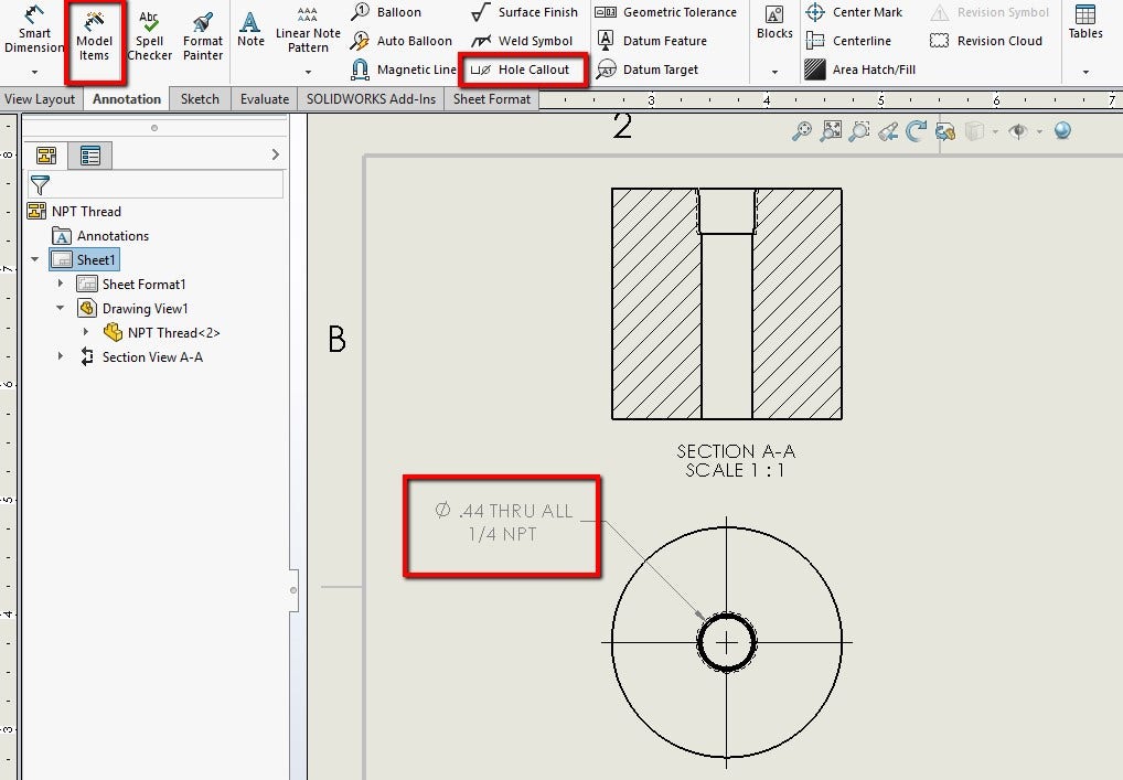
If there is no thread callout specified, another alternative can be used to show the NPT thread size on the drawing. Once the desired views have been added to the drawing, either use Model Items and check off Hole Callout or use the Hole Callout feature located in the Annotation tab of your drawing. The Hole Callout feature uses the geometry and information from the Hole Wizard to show the dimension. If the size of the thread is displayed with this method, you can notice in the example below, it displays the internal diameter of the through-hole as well as the NPT size.
Many CNC milling machine operators will express different opinions regarding their preferred type of cutting tool for a specific application because they tend to rely on tactics that have worked in the past. It is possible to achieve even better results by making a more informed choice of solid carbide.
In the meantime, check out our other blogs/vlogs for more information on SOLIDWORKS Flow Simulation and 3D Printing. Here are a couple of links to get your started:
Choosing the right tool is essential, and we at SCTools strive to provide you with the knowledge and experience to help you make the best choice for your application.
A deciding aspect may be the capacity to change insert corners after a particular lot or amount for process dependability, even though tooling with sophisticated coatings typically has excellent tool life. Additionally, indexable tooling provides a variety of radii, coatings, and substrates (such as PCD) that may enhance your application.
Hello Nikki, I came across this article and however helpful, My SW2018 doesn’t have larger than 3″ in the Hole wizard for Pipe threads. I am faced with making an 5″ aluminum pipe Cap on the CNC Mill, that I am not able to find locally. and not sure how to draw this or program this when it comes to cutting the threads. I will be thread milling. Not sure what diameter, depth of thread, taper angle, and depth of the actual thread to program. I do know that 5″ is 8 TPI. So that part is clear. Any help appreciated. Thank you, Tryon
National Pipe Thread Taper, commonly known just as NPT, is a U.S. standard for tapered threads used on threaded pipes and fittings. This standard is widely used all over North America. Pipe thread sizes are usually based on the inside diameter (ID) or flow size. The way to read an NPT size is the nominal inside diameter and the number of threads per inch. For example, if we have a 1/4-18 NPT, that means it is a 1/4 inch inside diameter and 18 threads per inch. If LH is added to the end, it means the pipe has a left-handed thread.
Small, challenging-to-manage chips produced by solid carbide end mills have the potential to damage or lengthen the time needed for maintenance in places like way covers. But because of the feed rate and cut depth, chips made with indexable tooling are typically heavier and easier to handle. Changes in the tools used can also make a difference.
The next step is the End Condition which defines the total length of the thread, it can be left as the default value or customized to a specific distance. Another option that can be checked on is the cosmetic thread under the Options menu. It can be set to With or Without Thread Callout.
Good evening Madam. My name is Frederic FOE. I read your paper. And I am writing to ask your assistance. I am writing from Cameroon (Central Africa). I actually work on a M.Sc project aiming at improving a local model of agricultural sprinkler. The first task of my work will consist in producing a 3D printed model of my supposedly improved sprinkler. Then I will have to use Ansys Fluent to apply CFD on that model. As I don’t have any experience on neither 3D Printing or CFD, I need your help to advise me as I proceed. Would you help me review my 3D Model before I print It ? I am using Solidworks to Model the Sprinkler. I plan to use an online 3D printing Service and I don’t know which one to contact. Thanks for your assistance.
Being from an area of Canada that is very heavily involved in the oil and gas industry, I end up talking about NPT fittings on a regular basis and I always get asked how to find the NPT thread in SOLIDWORKS. Luckily, the Hole Wizard feature inside of SOLIDWORKS already has the designated library of NPT sizes and we just need to look in the right place!
If the With Thread Callout option is selected, the specific thread callout can be customized or left as default. Click OK to accept the Hole Wizard feature. In order to edit the callout, right-click and edit the Hole Thread feature embedded in the Hole Wizard feature.
Thanks, but the title of this post is “creating NPT threads” which you have not done. You have created a callout for a thread.
For more information on SOLIDWORKS tips or if you have any questions, contact us at Hawk Ridge Systems today. Thanks for reading!
However, you might not base your decision on the initial dollar amount. The advantages of the cost savings could be outweighed by process reliability improvements such as chip management, tool adjustments, or using a more durable (reliable) setup.
Creating Custom Thread Tool Profiles in Solidworks – https://support.hawkridgesys.com/hc/en-us/articles/4419921661197-Creating-Custom-Thread-Tool-Profiles-in-Solidworks
Although numerous elements exist to consider, and each circumstance should be evaluated individually, price and reliability spring to mind when selecting when to utilize an indexable or solid carbide tool.
Once the 2D drawing is created, a view can be dropped into the drawing using the View Palette located in the Task Pane on the right-hand side of the user interface. With the option Import Annotations checked on, the thread callout mentioned above will show up with the view as it is dragged and dropped into the drawing.
At the bottom of the PropertyManager of the Hole Thread, the text can be edited to any note and can be later automatically imported in the 2D drawing of the model.

The title of the post is “Creating NPT Threads in SOLIDWORKS Using the Hole Wizard Feature” (emphasis on Hole Wizard Feature). I get where you are coming from however I would make a comment.


 0086-813-8127573