
Combined Drill & Countersinks-Carbide - drill and countersink combo
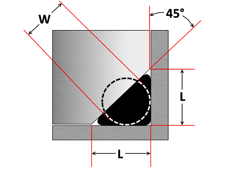
A static triangular crush seal groove is a simple design and ideal when space is limited and/or wall thickness is too thin for a conventional groove. It achieves the same sealing efficiency with either internal or external pressure. However there is very little void space and volume swell can easily lead to extrusion failure. O’rings in triangular crush grooves are permanently deformed once installed, therefore cannot be reused and are discarded after use.
Metric O’ring Groove Dimensions O-Ring Cross Section(L) Cylinder Groove Depth(G) Cylinder Groove Width No Back Up Rings(G) Cylinder Groove Width One Back Up Ring(G) Cylinder Groove Width Two Back Up Rings(L) Flange Groove Depth(G) Flange Groove Width(R) Radius without back up ring(R) Radius with back up ring 1.00.81.4––0.651.40.20.2 1.20.951.7––0.81.70.20.2 1.31.051.8––0.91.80.20.2 1.51.22.1––1.02.10.20.2 1.61.32.2––1.12.20.30.2 1.9 & 2.01.652.53.95.31.42.50.50.2 2.42.03.24.66.01.73.20.50.3 2.52.13.44.86.21.83.40.50.3 2.62.253.65.06.41.93.60.60.3 2.72.33.75.16.51.953.70.60.3 3.02.53.95.36.72.23.90.80.3 3.152.74.05.46.82.34.00.80.4 3.53.14.86.27.62.74.81.00.4 4.03.55.47.18.83.15.41.00.4 4.54.06.07.79.43.46.01.00.4 5.04.36.78.410.13.96.71.00.4 5.54.87.39.010.74.47.31.20.6 5.75.07.79.411.14.67.71.20.6 6.05.38.29.911.64.88.21.20.6 6.355.68.710.412.15.18.71.20.6 6.55.78.910.612.35.48.91.20.6 7.06.19.512.014.55.89.51.50.6 7.56.514.412.915.46.210.41.50.6 8.07.011.013.516.06.611.01.50.6 8.47.511.714.216.76.911.72.00.6 9.07.812.515.017.57.412.52.00.6 9.58.313.315.818.37.813.32.00.6 10.08.713.516.018.58.313.52.00.6 11.09.615.518.020.59.115.53.00.6 12.010.516.819.321.810.316.83.00.6 14.012.219.021.524.011.619.03.00.6 15.013.220.022.525.012.520.03.00.6 16.014.021.524.026.513.521.53.00.6
“You've got New Zealand, Japan and Mexico all looking, but KMT is the closest one to getting drill bit in the ground,” she says.
Static Cylinder Grooves O’ring Cross Section(L) Groove Depth Radial(L) Groove Depth AxialSqueeze Radial %Squeeze Axial %(E) Max Diametrical ClearanceG) Groove W 0 Back-up ±.005G) Groove W 1 Back-up ±.005G) Groove W 2 Back-ups ±.005R) Groove RadiusMax Eccentricity .070.050 – .052.050 – .05422–3219–32.004.095.140.207.005 – .015.002 .103.081 – .083.074 – .08017–2420–30.005.142.173.240.005 – .015.002 .139.111 – .113.101 – .10716–2320–30.006.189.210.277.010 – .025.003 .210.170 – .173.152 – .16215–2121–30.006.283.313.413.020 – .035.004 .275.226 – .228.201 – .21115–2021–29.007.377.410.540.020 – .035.005
Triangular Crush Groove Cross Section (W)±Groove Depth (L)± (-0) .070″±.003″0.092″+.003″ .103″±.003″0.136″+.005″ .139″±.004″0.184″+.007″ .210″±.005″0.277″+.010″ .275″±.006″0.363″+.015″ 1.50mm±0.08mm1.98mm+0.08mm 2.00mm±0.08mm2.64mm+0.08mm 2.50mm±0.08mm3.30mm+0.13mm 3.00mm±0.10mm3.96mm+0.13mm 4.00mm±0.13mm5.28mm+0.18mm 5.00mm±0.13mm6.61mm+0.25mm 6.00mm±0.15mm7.93mm+0.25mm 8.00mm±0.18mm10.57mm+0.38mm 9.00mm±0.18mm11.89mm+0.38mm
O’ring CSMinimum SqueezeGroove Width (G) .070 ±.003.005.080 .103 ±.003.006.110 .139 ±.004.007.160 .210 ±.005.008.240 .275 ±.006.010.315
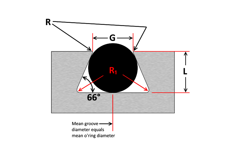
Half Dovetail Groove O’ring CSGroove Depth (L)Squeeze (%)Groove Width (G)Retainer Radius (R)Groove Radius (R₁) .070 ±.003.053 – .05523.064 – .066.005.015 .103 ±.003.083 – .08519.095 – .097.010.015 .139 ±.004.113 – .11518.124 – .128.010.031 .210 ±.005.173 – .17617.190 – .193.015.031 .275 ±.006.234 – .23815.255 – .257.015.062 .375 ±.007.319 – .32314.350 – .358.020.093
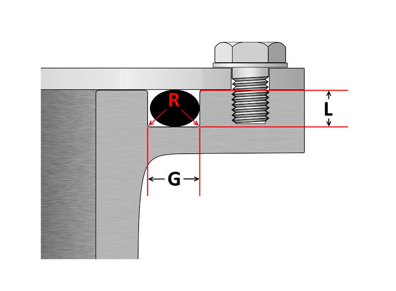
Groove Flange O’ring Cross Section(L) Groove DepthSqueeze (%)(G) Groove W Liquid ±0.005(G) Groove W Vacuum ±0.005(R) Groove Radius .070.050 – .05419–32.101 – .107.084 – .089.005 – .015 .103.074 – .08020–30.136 – .142.120 – .125.005 – .015 .139.101 – .10720–30.177 – .187.158 – .164.010 – .025 .210.152 – .16221–30.270 – .290.239 – .244.020 – .035 .275.201 – .21121–29.342 –.362.309 – .314.020 – .035
Note: Top radius (R) is a critical dimension; too small a radius can damage the seal during installation, while excess radius can lead to extrusion failure.
As important as the o’ring seal itself is the groove that the o’ring seats into. The groove must be designed to accommodate not just the o’ring size, but also its intended usage; be it dynamic or static operation, radial or axial loading, vacuum or high pressure.
On Wednesday night, new equipment - a powerful horizontal drill with an augur or drill bit - was flown in by military aircraft in three parts and assembled at the accident site.
In a face seal, a dovetail and half-dovetail groove are ideal for holding an o’ring in place during installation and operation. This can allow more streamlined maintenance and shorter downtime with less effort required to secure the seal during installation. Especially handy if the face seal is assembled upside-down. However, due diligence is required when designing a dovetail groove due to limited void space compared to a conventional square groove. This problem can be aggravated by volume swell. Therefore dovetail grooves are not recommended unless end use conditions and their effects upon the seal are thoroughly taken into consideration.
Dimensions apply to all laterally loaded o’rings in static face seal grooves for both liquid pressure and vacuum applications.
63RMS maximum: For non-critical sealing surfaces such as groove sides32RMS maximum: For static sealing on critical sealing surfaces such as groove base and top.16RMS maximum: For dynamic sealing surfaces and for sealing gases in a face type seal.
Dovetail Groove O’ring CSGroove Depth (L)Squeeze (%)Groove Width (G)Retainer Radius (R)Groove Radius (R₁) .070 ±.003.053 – .05523.057 – .061.005.015 .103 ±.003.081 – .08321.083 – .087.010.015 .139 ±.004.111 – .11320.113 – .117 .010.031 .210 ±.005.171 – .17318.171 – .175.015.031 .275 ±.006.231 – .23416.231 – .235.015.062 .375 ±.007.315 – .31916.315 – .319.020.093
The following information is a guide for o’ring groove dimensions for both static and reciprocating dynamic applications. The info is based on 70 Shore A Durometer hardness only.
Reciprocating Cylinder Grooves O’ring Cross Section(L) Groove DepthSqueeze %(E) Max Diametrical Clearance(G) Groove W 0 Back-up ±.005(G) Groove W 1 Back-up ±.005(G) Groove W 2 Back-ups ±.005(R) Groove RadiusMax Eccentricity .070.055 – .05715 – 25.004.095.140.207.005 – .015.002 .103.088 – .09010 – 17.005.142.173.240.005 – .015.002 .139.121 – .1239 – 16.006.1890.210.277.010 – .025.003 .210.185 – .1888 – 14.006.283.313.413.020 – .035.004 .275.237 – .24011 – 16.007.377.410 .540.020 – .035.005
The new equipment - a heavy-duty horizontal drill with an augur or with a drill bit - was flown in by military aircraft in three parts and was assembled at the accident site.
Due to PTFE’s (Teflon®) highly limited deflection ability, the following table has suggested groove dimensions for open face seal (flange) type grooves using imperial PTFE o’rings. PTFE o’rings in radially loaded closed grooves are generally not recommended, however if this is unavoidable, PTFE o’rings can be heated to around 100°C to allow them to become slightly flexible, aiding installation.


 0086-813-8127573