
Company - Harvey AI - team harvey
1. CHOOSE AN APPROPRIATE STEPOVEROptimized Roughing typically employs end mills with 5- to 9-flutes. End mills with fewer flutes have more space for chip formation, thus can utilize larger step-overs. Although the step-over of tools with fewer flutes can be higher, the traverse rate of the tool is decreased. Therefore, a balance must be struck where the optimum step-over and feed rate are utilized for each type of tool. The cutting data in this brochure has been specified based on extensive testing and experience and should serve as a good starting point for your application.2. USE STRONG, SECURE TOOL HOLDERS & FIXTURINGHigh-precision holders are crucial when Optimized Roughing to achieve maximum tool life. Run-out needs to be kept to less than 0.0004” to maximize tool life. This type of precision can be achieved by most shrink fit holders, milling chucks, high precision collet chucks, and select manufacturer’s end mill holders. A precise holder ensures the accuracy of the process, whereas a less secure holder will cause undesirable levels of vibration while Optimized Roughing at high feed rates.3. MAKE SURE YOUR MACHINE IS CAPABLE OF PERFORMINGMachine tools used for Optimized Roughing not only need to be able to achieve extremely high feed rates but also need to be able to process thousands of lines of code in a matter of seconds. This requires advanced look-ahead capabilities and processing systems found in newer machine tools. Rigidity throughout the machine tool from the spindle bearings all the way through to the ball screws ensures smooth cutting, consistent tool life, and unsurpassed part quality.4. CHOOSE A SUITABLE PROGRAMMING METHODIt is nearly impossible to program an Optimized Roughing strategy manually. Many companies provide state-of-the-art programming software. Careful consideration must be made when choosing the right software or software add-on. Not all software is created equal. For example, a programming software designed only for complex 3D high-speed milling may not be able to perform the complex radial moves inside of tight corners to maintain a consistent angle of engagement. This is one of the many keys to successful Optimized Roughing strategies.5. SELECT THE RIGHT DEPTH OF CUTTake advantage of the full flute length of the tool selected for the specific application. Maximizing depth of cuts above 2 times the diameter of the tool is common when Optimized Roughing. Smaller radial step-overs make such depths of the cut possible. A larger step-over would increase the amount of heat in the cut, which in turn will have a negative effect on tool life and performance. Therefore, rpm and feed rates must be reduced. A cut that is too deep, over 3 x D for instance, can create cutting pressures greater than what the tool can bear and possibly cause deflection. In this circumstance, chip splitters can minimize radial cutting pressure reducing deflection and aiding in chip control.6. FOLLOW RECOMMENDED CUTTING PARAMETERSAfter meticulous research and years of firsthand experience, we have developed specific recommended cutting parameters. Always to be used as a starting point, cutting data is optimized per tool design, specifications, and material groups. Modifications can be made depending on the application.
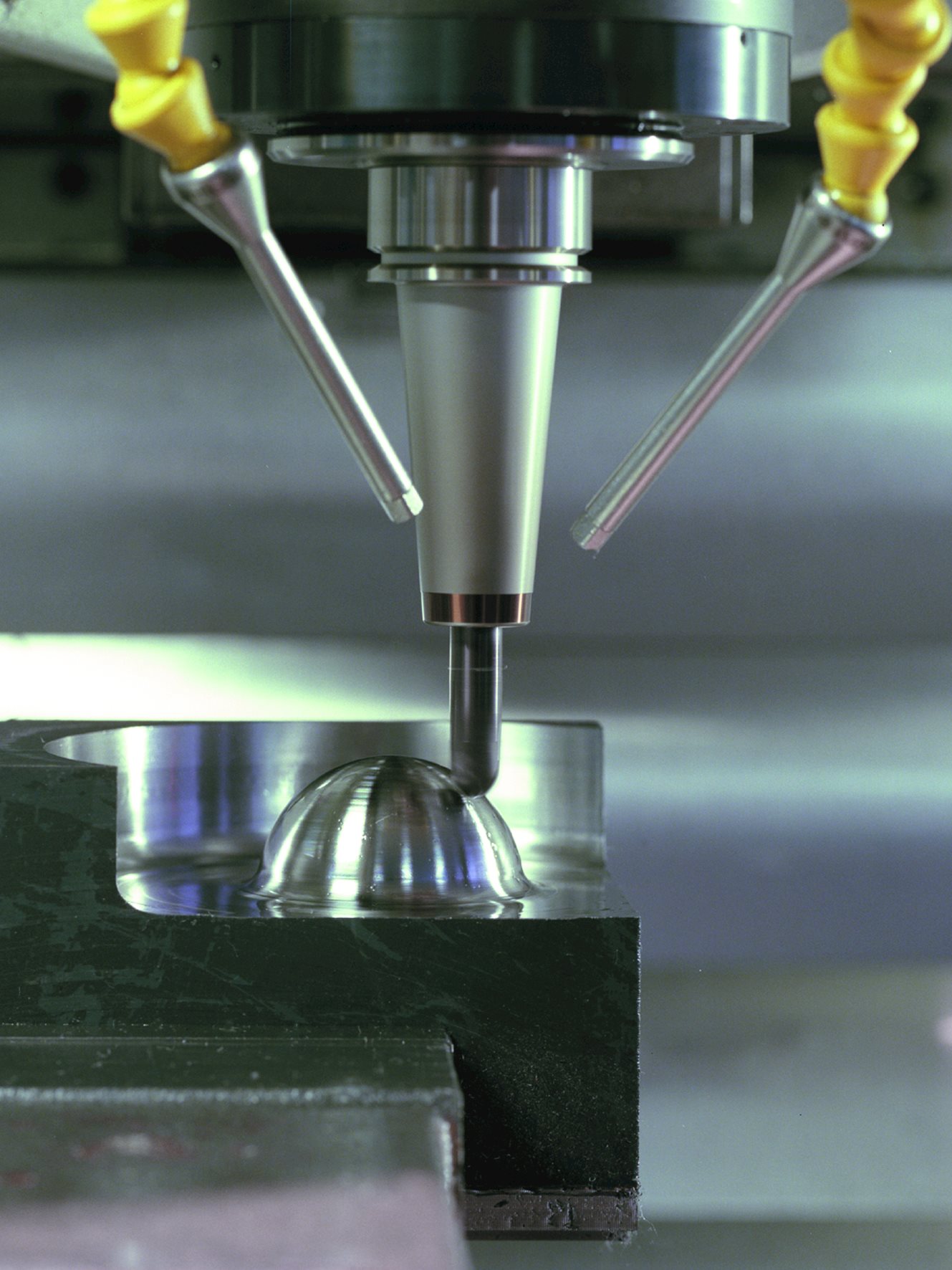
High-precision holders are crucial when Optimized Roughing to achieve maximum tool life. Run-out needs to be kept to less than 0.0004” to maximize tool life. This type of precision can be achieved by most shrink fit holders, milling chucks, high precision collet chucks, and select manufacturer’s end mill holders. A precise holder ensures the accuracy of the process, whereas a less secure holder will cause undesirable levels of vibration while Optimized Roughing at high feed rates.
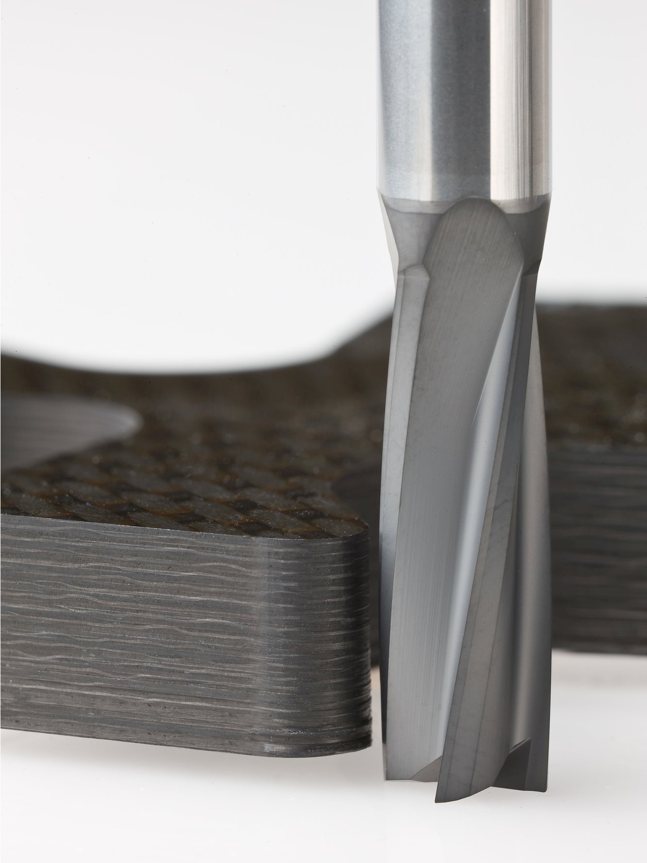
Optimized Roughing typically employs end mills with 5- to 9-flutes. End mills with fewer flutes have more space for chip formation, thus can utilize larger step-overs. Although the step-over of tools with fewer flutes can be higher, the traverse rate of the tool is decreased. Therefore, a balance must be struck where the optimum step-over and feed rate are utilized for each type of tool. The cutting data in this brochure has been specified based on extensive testing and experience and should serve as a good starting point for your application.
It is nearly impossible to program an Optimized Roughing strategy manually. Many companies provide state-of-the-art programming software. Careful consideration must be made when choosing the right software or software add-on. Not all software is created equal. For example, a programming software designed only for complex 3D high-speed milling may not be able to perform the complex radial moves inside of tight corners to maintain a consistent angle of engagement. This is one of the many keys to successful Optimized Roughing strategies.
Machine tools used for Optimized Roughing not only need to be able to achieve extremely high feed rates but also need to be able to process thousands of lines of code in a matter of seconds. This requires advanced look-ahead capabilities and processing systems found in newer machine tools. Rigidity throughout the machine tool from the spindle bearings all the way through to the ball screws ensures smooth cutting, consistent tool life, and unsurpassed part quality.
After meticulous research and years of firsthand experience, we have developed specific recommended cutting parameters. Always to be used as a starting point, cutting data is optimized per tool design, specifications, and material groups. Modifications can be made depending on the application.
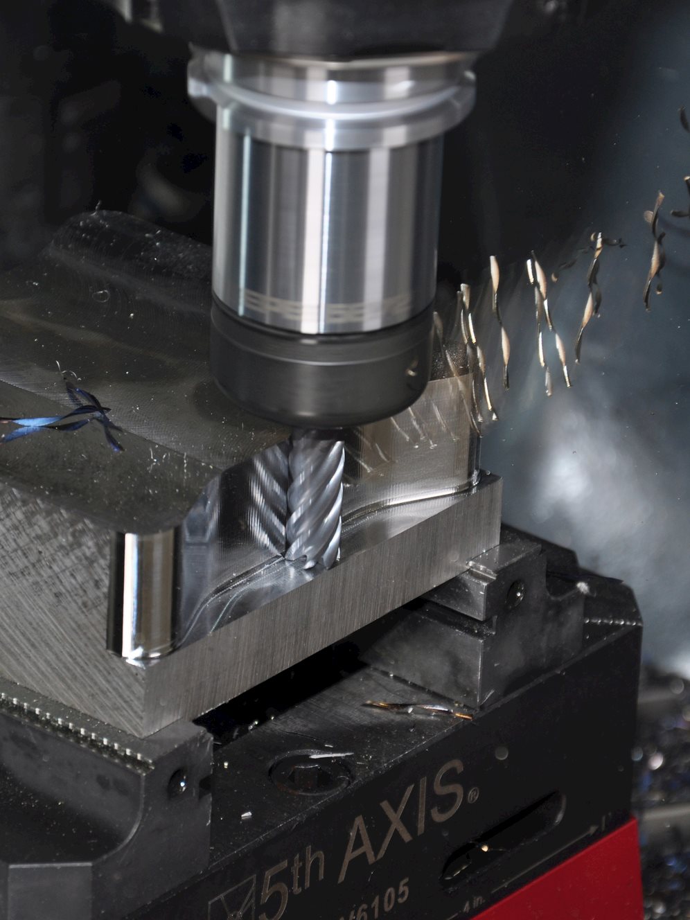
Take advantage of the full flute length of the tool selected for the specific application. Maximizing depth of cuts above 2 times the diameter of the tool is common when Optimized Roughing. Smaller radial step-overs make such depths of the cut possible. A larger step-over would increase the amount of heat in the cut, which in turn will have a negative effect on tool life and performance. Therefore, rpm and feed rates must be reduced. A cut that is too deep, over 3 x D for instance, can create cutting pressures greater than what the tool can bear and possibly cause deflection. In this circumstance, chip splitters can minimize radial cutting pressure reducing deflection and aiding in chip control.


 0086-813-8127573