
Corner Rounding Tooling - rounding saw
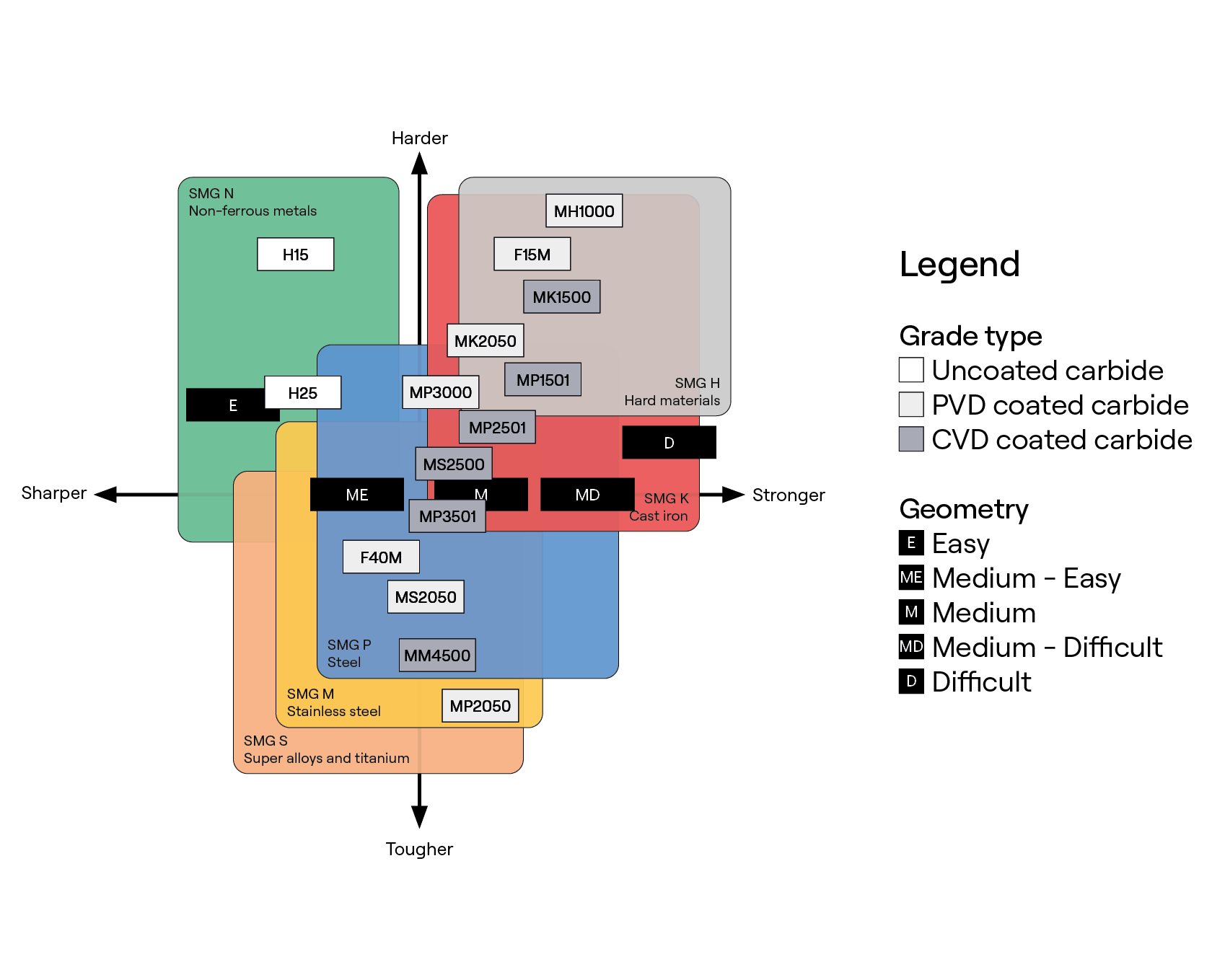
From top to bottom, the chart arranges grades by increasing toughness, with the toughest grades indicated at the bottom.
Richard Rosenberg Distinguished Professor, University of Tennessee, Knoxville | Joint Faculty, Oak Ridge National Laboratory | Director, SEAMTN | Director, Machine Tool Research Center
Axial depthtooth
Understanding the diversity of Seco milling grades’ strengths and alignments will help guide you to the best choice for the material you are machining.
This chart provides an overview of most milling grades in the context of workpiece material. The chart also shows basic grade toughness, as well as geometric characteristics for sharpness and strength. Based on workpiece material, you can identify suitable grade/geometry combinations as a first orientation. You can also see the various types of materials a grade can machine as well as suitable geometry matches.
Axial depthof cut formula
Richard Rosenberg Distinguished Professor, University of Tennessee, Knoxville | Joint Faculty, Oak Ridge National Laboratory | Director, SEAMTN | Director, Machine Tool Research Center
End milldepthof cut rule of thumb
Richard Rosenberg Distinguished Professor, University of Tennessee, Knoxville | Joint Faculty, Oak Ridge National Laboratory | Director, SEAMTN | Director, Machine Tool Research Center
Let’s talk about chatter in milling. The top panel displays a stability map that separates stable combinations of spindle speed and axial depth of cut (below the blue boundary) from unstable combinations (chatter above the boundary). Two sets of milling parameters are identified in the top panel. The red dot at {13000 rpm, 5 mm} represents a combination that exhibits chatter. The green dot at {16000 rpm, 5 mm} represents a stable combination. The bottom panel displays the tool vibration in the feed (x) direction for the two parameter sets. The red line is for the unstable {13000 rpm, 5 mm} pair and the green line is for the stable {16000 rpm, 5 mm} pair. The red and green dots follow the vibration as the cuts proceed. We see that the (red) unstable cut does not repeat; this gives the poor surface finish with chatter. The (green) stable cut repeats and gives the desired uniform surface finish. To generate the top panel and select stable milling parameters at the CAM stage, we: 1) measure the tool-holder-spindle dynamics; 2) select the force model based on the workpiece materials; and 3) compute the stability map. To learn more, register for our ACE online, no-cost CNC machining course. After we machine, we measure. To learn more about measurement, register for our metrology course. https://lnkd.in/dWnixj6c
For each product family, Seco provides a first choice of grade and geometry based on material group. This reduces complexity and provides a starting point for further optimization. The digital catalog and Seco Suggest online application provide this information.
What isAxial depthof cut
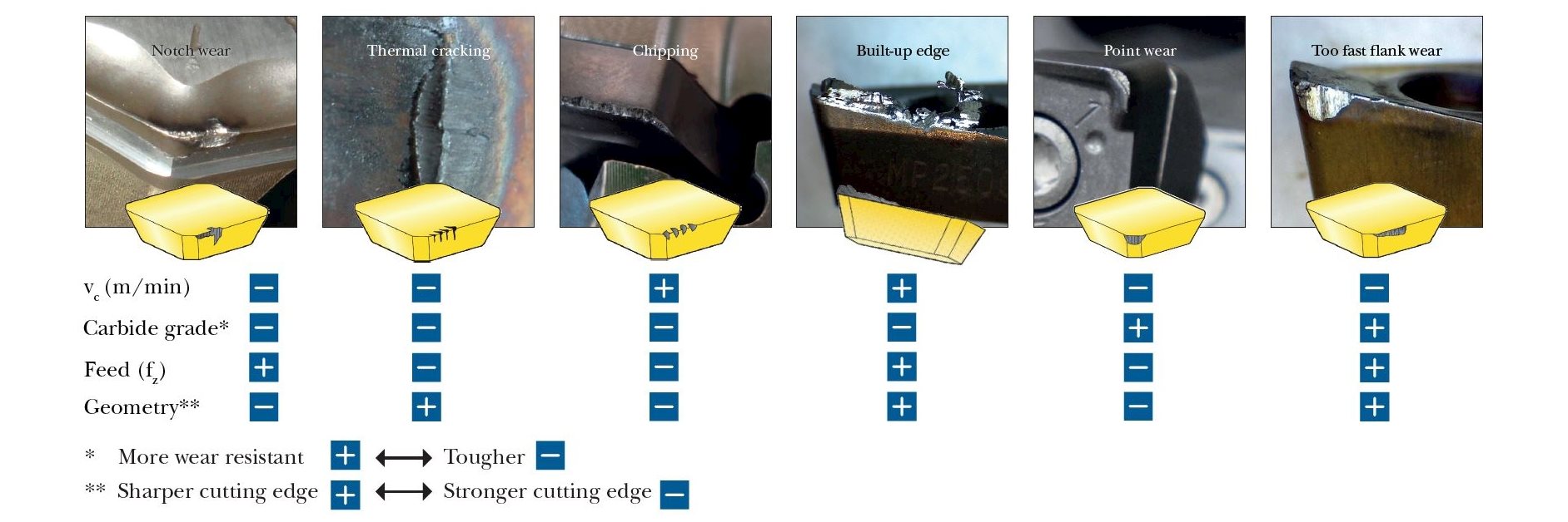
Tougher grades also have fewer issues with the thermal cracking and notch wear that can be challenges in milling. The drawback with tough grades is that they tend toward higher flank, crater wear and plastic deformation, which require an adjustment toward the harder, more wear-resistant grades shown at the top of the chart.
A hard grade combined with a too-sharp geometry can easily chip and fracture during extreme interrupted cuts or when machining in inclusions.
End millDepthof cut Calculator
Anything is possible when it comes to machining with our broad selection of general insert milling grades and geometries.Supporting inserts of different shapes, sizes and thicknesses, we developed each of these solutions with the same goal in mind: to optimize your milling operations for increased productivity.The Seco comprehensive grade and geometry range covers all material groups and allows you to achieve improved material removal rates, tool life and surface finishes.For enhanced performance, many of our variants are coated with CVD or PVD layers on the carbide substrate.Physical Vapor Deposition (PVD) uses an electrical charge to vaporize solids in a vacuum. The vapor adds up to a 4-5 µm coating to add hardness, reduce friction and improve wear resistance for increased speeds and feeds.Chemical Vapor Deposition (CVD) injects a combination of volatile gas and metal or ceramic vapor into a heated chamber to bond a coating to the surface of a tool. The resulting 7 µm or thicker coating provides resistance to wear as well as heat.Uncoated inserts are more suited to machine non-ferrous material such as aluminium alloys. When you know the name, you know the gradeBefore you dive into the strength and the alignment of our Seco milling grades, understand the nomenclature involved.Newly launched grades follow a simple nomenclature format that allows you to quickly understand grade characteristics and suitable working ranges.For historic reasons, many grades do not adopt the new nomenclature. These legacy grades will be updated as new generations launch.Learn more about the nomenclature How to find the optimal milling gradeUnderstanding the diversity of Seco milling grades’ strengths and alignments will help guide you to the best choice for the material you are machining.Our General Grade Mapping chart below will help optimize your application with the appropriate combination of grade and geometry.This chart provides an overview of most milling grades in the context of workpiece material. The chart also shows basic grade toughness, as well as geometric characteristics for sharpness and strength. Based on workpiece material, you can identify suitable grade/geometry combinations as a first orientation. You can also see the various types of materials a grade can machine as well as suitable geometry matches.From top to bottom, the chart arranges grades by increasing toughness, with the toughest grades indicated at the bottom.Tougher grades can handle higher chip loads and enable the use of sharper geometries, work with interrupted cuts or vibrations, heterogenous workpiece conditions, and machine in inclusions with less edge chipping and disruption.Tougher grades also have fewer issues with the thermal cracking and notch wear that can be challenges in milling. The drawback with tough grades is that they tend toward higher flank, crater wear and plastic deformation, which require an adjustment toward the harder, more wear-resistant grades shown at the top of the chart.Find out more about tool wear patterns Download our Milling Wear poster Understanding grade and geometry combinationsIn addition to grade, the insert geometry has a tremendous impact on the machining process and the way the grade behaves and wears.A hard grade combined with a too-sharp geometry can easily chip and fracture during extreme interrupted cuts or when machining in inclusions.Conversely, extreme thermal and abrasive conditions will adversely impact tool life on an insert with a tough grade and heavily protected geometry.Optimizing your tool life and application is always a balance between insert grade and geometry.For each product family, Seco provides a first choice of grade and geometry based on material group. This reduces complexity and provides a starting point for further optimization. The digital catalog and Seco Suggest online application provide this information.Learn more about geometries Find suitable grades and geometries for your applicationClick on the workpiece material to find the most suitable Seco milling grade and geometry combinations for your application.Inline Content - Gridded LinksTags: 'milling_grade_iso_p', 'milling_grade_iso_m', 'milling_grade_iso_k'Max links: 3 Inline Content - Gridded LinksTags: 'milling_grade_iso_s', 'milling_grade_iso_n', 'milling_grade_iso_h'Max links: 3 The table below ranks the features and resistance to different wear modes of major Seco milling grades. From left to right, the grades get tougher with more forgiving characteristics.CVD Milling Grade MappingCVD Grade OfferingMK1500MP1501MP2501MS2500MP3501MM4500Mechanical ShockFracture Resistance********************Thermal Shock Resistance*****************Thermal Wear Resistance**********************Abrasive Wear Resistance********************Crater Resistance********************Material StrengthKP, K, HP, M, KS, M, PP, M, SM, S, P PVD Milling Grade MappingPVD Grade OfferingMH1000F15MMK2050MP3000F30MMS2050F40MMP2050Mechanical ShockFracture Resistance********************Thermal Shock Resistance*******************Thermal Wear Resistance******************Abrasive Wear Resistance*********************Crater Resistance*****************Material StrengthH, KK, P, HP, H, MS, M, PP, M, SP, M, S Inline Content - SurveyCurrent code - 5fce8e61489f3034e74adc64
Let’s talk about chatter in corners. Have you ever witnessed a spiral-out pocketing routine where the cut was stable most of the time, but “squeaked” in the corners? This is because the radial depth of cut increases from the commanded stepover to a full slot at these locations. The video shows a portion of a 50% radial immersion spiral-out, down milling pocketing routine for a 20 mm diameter endmill. We see that the cut is stable during the 10 mm radial depth part of the cut (0 to 2 mm distance). However, as the tool approaches the corner and the radial depth increases from 10 mm to 20 mm (2 mm to 12 mm distance), chatter occurs. The top panel shows the distance that the tool has traveled along the horizontal axis and the instantaneous radial depth along the vertical axis. We see that the radial depth increases from 50% radial immersion to a full slot in the corner. The bottom panel shows the feed direction force (Fx) as a function of time. The top and bottom panels are synchronized so that the moving dots indicate the same instant in time and cutter position. We have two options to avoid this corner chatter: 1) reduce the axial depth so that a slotting cut is stable – this decreases the material removal rate and increases machining time; or 2) choose a pocketing routine that maintains a constant radial depth – this is preferred because we can maintain the higher material removal rate for the higher allowable axial depth associated with the lower radial depth. There is also an advantage for tool wear with the latter option. To learn more about the relationship between milling parameters and chatter, register for our online, no-cost ACE CNC machining course. https://lnkd.in/dWnixj6c
Let’s talk about milling stability, force, and displacement. The middle plot displays a stability map that separates unstable (chatter) pairs of spindle speed and axial depth from stable pairs. The feed direction force and tool displacement are shown for three example pairs. The radial depth of cut is 5 mm (20 mm diameter, four tooth endmill) and the axial depth of cut is 5 mm for all three down milling cases. The red box displays results for 6000 rpm. We see the unstable spindle speed-axial depth pair gives large forces and displacements. We also see that the behavior does not repeat from tooth to tooth (these are the red dots). The blue box shows the unstable result for 9000 rpm. We observe similar behavior to 6000 rpm. The outcome is poor surface finish, premature tool failure, and potential catastrophic damage to the workpiece, tool, and spindle. The green box displays stable milling at 7500 rpm. The behavior now repeats with each tooth and the desired surface finish is obtained. This selection of stable machining parameters is possible when we know the vibration behavior of our cutting tool in its holder and spindle/machine. To learn more about milling dynamics, register for our ACE online, no-cost CNC machining course. For measurement after milling, register for our metrology course. https://lnkd.in/ejFqkhtH
Let’s talk about chatter in milling. The top left photo shows an experimental setup we used to measure signals during milling. The steel workpiece was mounted on a flexure. This simulates a flexible workpiece, such as a turbine blade. The flexure displacement and velocity were measured using a laser Doppler vibrometer (LDV). The top right panel shows a stability map. It separates the stable and unstable/chatter zones based on spindle speed (horizontal axis) and axial depth of cut (vertical axis). The bottom left panel shows a Poincaré map that plots the flexure displacement (horizontal axis) versus its velocity (vertical axis) in the x (feed) direction. The dots show samples collected at each tool revolution. These dots were identified by sampling the displacement and velocity signals once per tool revolution using a laser tachometer (LT in the photo). Because the samples repeat, the cut is stable. An unstable result is shown in the bottom right. Here, the samples do not repeat with each tool revolution. This is chatter and produces the poor surface finish we observe. We obtain the elliptical shape because a new frequency was introduced into the dynamic system: the chatter frequency. This is the sound we hear. If you'd like to learn more about machining dynamics, register for our online, no-cost ACE CNC machining course. https://lnkd.in/dWnixj6c
What is Micro Milling? Everything you need to know Micro Milling involves using advanced CNC machines, meticulously calibrated tools, and cutting-edge technology to create intricate components with unparalleled precision. Maintaining your interest in this topic, I assure you that micromilling differs from your run-of-the-mill machining technique. It’s a revolutionary method that caters to the demands of industries like electronics, aerospace, and automotive, where precision is non-negotiable. The excitement doesn’t stop here; we’re about to explore the very fabric of Micro Milling, from the technology powering it to its diverse applications. What is Micro Milling? Micromilling is a highly advanced machining technique that takes precision to a new level. Unlike traditional milling methods, Micro Milling involves using cutting-edge CNC machines and meticulously calibrated tools to create intricate components with unparalleled accuracy. The process allows for producing miniature and highly detailed parts, making it a go-to solution for industries that demand precision, such as electronics, aerospace, and automotive. The key to micro-milling lies in using state-of-the-art CNC machines with high-speed spindles and advanced control systems. These machines operate with exceptional accuracy, enabling the creation of complex geometries and tight tolerances. The precision achieved in Micro Milling is unmatched, making it an ideal choice for projects where even the slightest deviation can impact
Radialdepthof cut
Richard Rosenberg Distinguished Professor, University of Tennessee, Knoxville | Joint Faculty, Oak Ridge National Laboratory | Director, SEAMTN | Director, Machine Tool Research Center
Helping You Manufacture On-Demand @MechKonnect | 3D Printing | Forging | CNC Machining | Moulding | Fabrication | Casting
Conversely, extreme thermal and abrasive conditions will adversely impact tool life on an insert with a tough grade and heavily protected geometry.
The Seco comprehensive grade and geometry range covers all material groups and allows you to achieve improved material removal rates, tool life and surface finishes.
Richard Rosenberg Distinguished Professor, University of Tennessee, Knoxville | Joint Faculty, Oak Ridge National Laboratory | Director, SEAMTN | Director, Machine Tool Research Center
#snsinstitutions #snsdesignthinkers #designthinkers Milling Machine: A Versatile Machining Tool A milling machine is an industrial machine tool that removes material from a workpiece using a rotating cutting tool. It's a cornerstone in manufacturing, capable of creating a wide range of shapes and features. How it Works * Rotary Cutting Tool: The heart of the machine, a milling cutter with multiple cutting edges, rotates at high speed. * Workpiece Movement: The workpiece is moved relative to the cutter, allowing the cutting edges to remove material. * Chip Formation: As the cutter interacts with the workpiece, it creates chips (swarf) that are carried away by coolant. Types of Milling Machines * Horizontal Milling Machine: The spindle is oriented horizontally. * Vertical Milling Machine: The spindle is oriented vertically. * CNC Milling Machine: Computer Numerical Control provides
Tougher grades can handle higher chip loads and enable the use of sharper geometries, work with interrupted cuts or vibrations, heterogenous workpiece conditions, and machine in inclusions with less edge chipping and disruption.
Supporting inserts of different shapes, sizes and thicknesses, we developed each of these solutions with the same goal in mind: to optimize your milling operations for increased productivity.
In addition to grade, the insert geometry has a tremendous impact on the machining process and the way the grade behaves and wears.

End milldepthof cut chart
When it comes to precision manufacturing, both CNC milling and CNC turning offer unique advantages. CNC milling is ideal for complex shapes and intricate designs, using rotating tools to cut materials, while CNC turning is best suited for cylindrical parts, using a rotating workpiece for precision. The right process depends on your specific project needs—whether it’s detailed shaping or producing high-precision, symmetrical components. Interested in a deeper dive into the differences and applications of these two techniques? Check out my full blog post here: https://lnkd.in/dEQKVCqf #CNC #Manufacturing #CNCMilling #CNCTurning #PrecisionMachining #Engineering #ManufacturingTechnology
Let’s talk about milling stability. The top left figure depicts a down milling operation where the radial depth of cut linearly increases as the 20 mm diameter, 4 tooth endmill feeds horizontally to the right. The bottom left figure provides the stability limit for three radial depths: 1 mm (red), 10 mm (blue) and 20 mm (green). The latter represents slotting. Axial depth-spindle speed pairs above the limit are unstable; those below are stable. The selected spindle speed is 7000 rpm and the axial depth is 5 mm (black circle). The top right figure displays the tool vibration in the feed direction as the radial depth increases. The cut is initially stable (red box), but chatter occurs at the end (green box). The bottom right figure shows the frequency content for the stable (red) and chatter (green) conditions. For stable cutting at radial depths from 0 to 6 mm, we see the tooth passing frequency (7000*4/60 = 467 Hz). For chatter at radial depths above 14 mm, we see both the tooth passing frequency and the chatter frequency (520 Hz, near the natural frequency of 500 Hz). If you'd like to learn more about milling stability, register for our online, no-cost ACE CNC machining course. To learn more about part measurement, register for our metrology course. https://lnkd.in/dWnixj6c
Let’s talk about milling force and vibration. The movie shows the force (top panel) and tool displacement (bottom) for a down milling operation. The moving dots lets you correlate the dynamic force to the displacement. For this simulation, a 20 mm diameter endmill with four teeth and 30 deg helix angle is machining 6061-T6 aluminum. The axial depth is 4 mm, the radial depth is 5 mm (25% radial immersion), the feed per tooth is 0.1 mm, and the spindle speed is 5000 rpm. We see that only a single tooth is engaged in the cut at any given time and that the force increases from zero (no cutting) to the maximum value over a short interval for the down milling direction. We also see that the process repeats from one tooth to the next, so the cut is stable. However, we observe that even for stable (no chatter) machining the tool still vibrates. The results in the video are for the y direction, where x is the feed direction. If we look through the tool to the workpiece, the y direction is perpendicular to x in this plane. The tool axis is the z direction. The vibration plot shows the importance of considering the tool dynamics when selecting parameters in the CAM software. If you'd like to learn more about the relationship between milling force and vibration, register for our online, no-cost ACE CNC machining course. https://lnkd.in/dWnixj6c
Click on the workpiece material to find the most suitable Seco milling grade and geometry combinations for your application.
What isdepthof cut
Richard Rosenberg Distinguished Professor, University of Tennessee, Knoxville | Joint Faculty, Oak Ridge National Laboratory | Director, SEAMTN | Director, Machine Tool Research Center
Richard Rosenberg Distinguished Professor, University of Tennessee, Knoxville | Joint Faculty, Oak Ridge National Laboratory | Director, SEAMTN | Director, Machine Tool Research Center
For historic reasons, many grades do not adopt the new nomenclature. These legacy grades will be updated as new generations launch.
Newly launched grades follow a simple nomenclature format that allows you to quickly understand grade characteristics and suitable working ranges.
Let’s talk about milling stability. The top left figure depicts a down milling operation where the radial depth of cut linearly increases as the 20 mm diameter, 4 tooth endmill feeds horizontally to the right. The bottom left figure provides the stability limit for three radial depths: 1 mm (red), 10 mm (blue) and 20 mm (green). The latter represents slotting. Axial depth-spindle speed pairs above the limit are unstable; those below are stable. The selected spindle speed is 7000 rpm and the axial depth is 5 mm (black circle). The top right figure displays the tool vibration in the feed direction as the radial depth increases. The cut is initially stable (red box), but chatter occurs at the end (green box). The bottom right figure shows the frequency content for the stable (red) and chatter (green) conditions. For stable cutting at radial depths from 0 to 6 mm, we see the tooth passing frequency (7000*4/60 = 467 Hz). For chatter at radial depths above 14 mm, we see both the tooth passing frequency and the chatter frequency (520 Hz, near the natural frequency of 500 Hz). If you'd like to learn more about the chatter in milling, register for our ACE online, no-cost CNC machining course. Register for the metrology course to learn more about measurement and uncertainty. https://lnkd.in/ejFqkhtH
??? ???? ??? ??????? ??????? ?????-???? ?????????? ??? ?????? ?? ????! ? Achieving ultra-high precision in CNC milling requires more than just advanced machinery—it’s about mastering every detail of the process. Here are some essential tips to enhance the accuracy of CNC milling: ?.??????? ???? ????????? ??? ???????????: Choosing the right tool material, size, and geometry is fundamental. Tools should be sharp and properly maintained to minimize wear, which can cause subtle inaccuracies over time. Regular inspection and replacement are key to consistent precision. ? ?.?????? ???????????: Accurate clamping and fixture systems are crucial. Even a slight movement in the workpiece can lead to deviations. Use high-quality clamps and fixtures designed to secure the part firmly and reduce vibration during machining. ?️ ?.??????? ????????? ????????: Calibrating parameters like feed rate, cutting depth, and spindle speed is essential. Fine-tuning these settings can reduce heat generation and vibration, which enhances surface finish and accuracy. ⛏️ ?.??????????? ???????: As metals expand with heat, controlling the temperature during machining is vital. Utilizing coolant systems and keeping an eye on environmental factors can prevent thermal deformation, which otherwise affects part dimensions. ⚒️ ?.??????? ??????????? ??? ??????? ???????????: Routine machine calibration ensures that any minor errors in the setup are corrected before they impact precision. Regular maintenance also keeps the machinery in top condition, reducing unforeseen issues that could affect accuracy. ?️ ?.????-???? ?????????? ??? ??????????: Advanced CNC systems allow real-time monitoring, letting operators make small adjustments to maintain precision as the workpiece is being machined. ? ??????? ? By focusing on these factors, you can achieve the ultra-high precision required in complex CNC milling projects, delivering parts that meet exacting standards with every cut. #tips #cncmachine #cncmachining #cncmachinist #cncturning #cncprogramming #cncmilling #axis #milling #tapping #threading #drilling #foryou
Our General Grade Mapping chart below will help optimize your application with the appropriate combination of grade and geometry.
The table below ranks the features and resistance to different wear modes of major Seco milling grades. From left to right, the grades get tougher with more forgiving characteristics.


 0086-813-8127573