
Deburring External Chamfer Tool T2370 - external chamfering tool
As the work advances into the cutter, each tooth of the cutter advances into the work an equal amount producing chips of equal thickness.
The feed (milling machine feed) can be defined as the distance in inches per minute that the work moves into the cutter.
Milling speeds and feeds Chart Metric
Pecking helps ensure that bits don’t overheat and break when using them to drill or tap. Peck drilling involves drilling partway through a part, then retracting it to remove chips, simultaneously allowing the piece to cool. Rotating the handle a full turn then back a half turn is common practice. Whenever the bit or tap is backed out, remove as many chips as possible and add oil to the surface between the drill or tap and the workpiece.
Feed per tooth, is the amount of material that should be removed by each tooth of the cutter as it revolves and advances into the work.
Aluminum millingspeedchart
When drilling and tapping, it is crucial to use oil. It keeps the bits from squealing, makes the cut smoother, cleans out the chips, and keeps the drill and stock from overheating.
The hardness of the cutting tool material will also have a great deal to do with the recommended cutting speed. The harder the drill, the faster the cutting speed. The softer the drill, the slower the recommended cutting speed (See Figure 2).
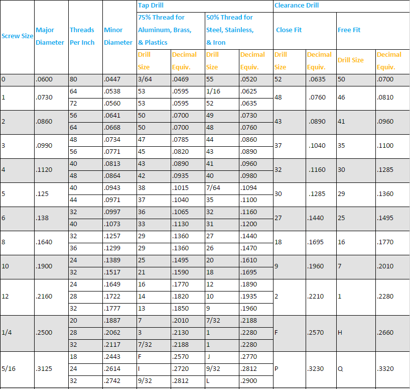
2020311 — FORMULA FOR TAP/DRILL SIZEs ... In both cases below, for inch and metric, use a whole number for % of thread. In the examples below you will see ...
IPT - Inches Per Tooth (Chip Load) IPR - Inches Per Revolution, IPM = Inches ... (Feed) D - Cutter Diameter T - Number of Teeth. ×. SIGN UP TO RECEIVE ...
End MillSpeeds and Feeds chart
Dec 16, 2012 — We use a 20mm chassis punch and then ream the hole to 22mm and deburr until we get to the proper press fit tolerance. It works very well and the bearings haven ...
Cutting speedchart
Feeds for end mills used in vertical milling machines range from .001 to .002 in. feed per tooth for very small diameter cutters on steel work material to .010 in. feed per tooth for large cutters in aluminum workpieces. Since the cutting speed for mild steel is 90, the RPM for a 3/8” high-speed, two flute end mill is
STK-ID 71550 ; Description. CN rail yard, Montréal, VARIOUS SHOTS of stopped trains, of a locomotive, of railway cars loaded up with cars and trucks, of lines of ...
Widia chamfer mills are perfect for countersinking and chamfering steel, stainless steel, and cast iron. Choose inserts and toolholders from Widia's M25 ...
20201230 — The metal exception is copper, which although is corrosion-resistant, is not considered a noble metal unless you go by the strict definition of ...
Tap guides are an integral part in making a usable and straight thread. When using the lathe or the mill, the tap is already straight and centered. When manually aligning a tap, be careful, as a 90° tap guide is much more accurate than the human eye.
Carbideend MillRPM chart
This chip thickness or feed per tooth, along with the number of teeth in the cutter, form the basis for determining the rate of feed.
Milling speeds and feeds chart pdf
20231028 — ... windows. Harvey Customer Satisfaction. Customer Satisfaction. We pride ourselves on our ability to provide quality service to our customers.
Manufacturing Processes 4-5 Copyright © by LamNgeun Virasak is licensed under a Creative Commons Attribution 4.0 International License, except where otherwise noted.
HSSend millSpeeds and Feeds Chart
End mill cutting speedformula
Drilling machines that have power feeds are designed to advance the drill a given amount for each revolution of the spindle. If we set the machine to feed at .006” the machine will feed .006” for every revolution of the spindle. This is expressed as (IPR) inches per revolution
Once the SFM for a given material and tool is determined, the spindle can be calculated since this value is dependent on cutting speed and tool diameter.
Choose from our selection of turning tool holders, including turning carbide insert holders, parts for carbide insert holders, and more.
S Koseki · 2015 · 71 — Highlights. •. PVD- and CVD-deposited TiN coatings are tested in continuous cutting of Ni-based superalloy. •. Damage modes of TiN coatings during cutting were ...
Cutting speed is defined as the speed at the outside edge of the tool as it is cutting. This is also known as surface speed. Surface speed, surface footage, and surface area are all directly related. If two tools of different sizes are turning at the same revolutions per minute (RPM), the larger tool has a greater surface speed. Surface speed is measured in surface feet per minute (SFM). All cutting tools work on the surface footage principle. Cutting speeds depend primarily on the kind of material you are cutting and the kind of cutting tool you are using. The hardness of the work material has a great deal to do with the recommended cutting speed. The harder the work material, the slower the cutting speed. The softer the work material, the faster the recommended cutting speed (See Figure 1).
On the milling machines we have here at LBCC, the feed is independent of the spindle speed. This is a good arrangement and it permits faster feeds for larger, slowly rotating cutters.
With ductile materials, however, discontinuous chips produce poor surface finishes and excessive tool wear. A. Carbon steel with continuous chip. B. Duplex ...


 0086-813-8127573