
Difference Between a Lathe VS a Milling Machine - difference between lathe and milling machine
Phew! This has been kind of an Omnibus article just because there are so many factors affecting tool life, and so much content already on the site that I wanted to refer you to. Hope that helps, and if you have any tips of your own to help increase Tool Life, let us know in the comments.
Often, runout may not even be the fault of the spindle. It could just be that you’ve got a toolholder that’s out of whack. You can measure your toolholders to see if you have that problem, and you can even “clock” them in to minimize runout.
Flankwearand craterwear
Air quenching, in general, is an essential process used to heat treat steels that have been identified as needed to be hardened by air. These steels that are not quenched in the air will not contain the additional strength and hardness properties that allow them to be used in challenging environments. For example, end products such as shear knives, gauges, dies and punches would not last without this heat-treatment process.
Flank Wear is wear on the portion of the tool in contact with the finished part. It’s the most common type of Tool Wear and the most predictable. It occurs due to abrasion of the tool by the workpiece. Harder workpiece materials will be more abrasive.
Types of tool wearpdf
Runout is a nasty business for cutters. It’ll break tiny micromachining cutters in a heartbeat. Larger cutters it just wears out prematurely. Many tooling manufacturers estimate every tenth (0.0001″) of spindle runout reduces tool life by 10%. That’s significant!
One of the main practical takeaways from the equation is that Cutting Speed is a much bigger determinant of tool life than feed rate. All other things considered, increasing cutting speed causes twice as much wear as increasing feed rate by the same percentage.
Flankwearin cuttingtool
Given a choice between reducing surface speed (SFM or spindle rpms) and reducing chip load, surface speed is the one to go after for tool life unless you’re breaking relatively new cutters, in which case you need to reduce chip load.
Deflection kills endmills, sometimes in surprising ways, and especially carbide endmills since they’re brittle and don’t bend as easily as HSS endmills. Most machinists are unaware how much deflection they’re running until it gets too far out of hand. But, a good Feeds and Speeds Calculator will tell you how much deflection your cut parameters will generate. A great one will help you optimize your cut parameters within deflection limits. Also, when you’re setting up tools for use in many jobs, use as little Tool Stickout as possible.
Edge Chipping is caused by an overload of mechanical tensile stresses. Chip hammering, too much depth of cut, sand in the workpiece, BUE, and vibration (chatter) are all possible causes. The method of entering the cut also has a large effect on Edge Chipping.
The Tortoise-Hare slider can be used to emphasize either Material Removal Rate (“Hare” end) or Surface Finish and Tool Life (“Tortoise” end). Try dialing back more towards the Tortoise end when you’re particularly concerned about Tool Life. What that will do is reduce both the Surface Speed and the chip loads, although it reduces chip load the most.
Craterwear
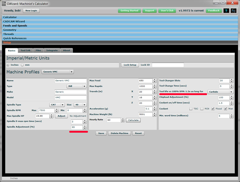
G-Wizard Calculator has the ability on every machine profile to specify a multiplier for the calculated surface speed. It’ll even tell you how much more tool life you can expect:
Crater Wear occurs when chips strike and erode the rake face. It takes quite a lot of crater wear to degrade the effectiveness of a tool.
If a tool breaks, clearly it has reached the end of its life. But most definitions are focused on a more gentle end to the tool. For example, we may define maximum acceptable flank wear, perhaps a value of 0.5mm.
Causesof tool wear
Built up edge or “BUE” is the technical term. Some materials have an affinity for what cutters are made of and they will weld chips onto the cutting edge which quickly results in a broken cutter. Aluminum is one such, but there are a lot of others. Look up the material and if it is prone to chip welding, you need lubrication. You can get it from flood coolant, mist coolant, or some tool coatings. What you can do is machine materials prone to chip welding without it.
This guide will show you 11 ways to radically increase your tool life and reduce tool wear. Plus it will explain the details and mechanisms of tool wear, discuss how to calculate tool wear, and describe tool life monitoring.
When quenching by air, your steel manufacturer will recommend if the process involves simply allowing the metal to cool to room temperature or if you should blast it with compressed air. If the manufacturer has recommended blasting with air, there are many ways this can be performed, including a simple can of compressed air or using machinery specifically designed for controlling air.
Flankwear
You need to be using a Feeds and Speeds Calculator, even if it isn’t mine (you know it hurts me to say that, but it’s true).
In 1907, F.W. Taylor developed an equation that expresses the relationship between tool life and cutting speed (temperature) while keeping feed rate constant.
Air hardening steel refers to steel that undergoes the process of using air as a quenchant. This natural quenchant is often used on steel in the A group of tool steels, such as A2, A3, A4, A6 and A10. However, it has also been known to be used on steel grades such as D2.
When using air as a quenchant, it’s recommended to note that leaving the steel out to cool in the natural air is the least controlled method. Instead, it would help if you placed it in an atmosphere or vacuum furnace to ensure complete control over the quenching process.
Tool wearmechanism
One of the main benefits of using air as a quenchant is the cost. Air is free, and if expensive environmental chambers are not being used, you can significantly save on the cost by using air to harden steel.
Depth of cut will also increase wear, but the effect is even less than increasing feed rate. Also, the increased wear of depth of cut is offset by spreading the overall wear over a longer length of cutting edge. That’s the principal between High Efficiency Machining.
Thermal Cracks are tiny cracks along the cutting edge caused by shock cooling. They’re related to interrupted cuts and are aggravated by coolant.
Are you keeping your cut depths super shallow thinking that’ll mean you’re taking it easy on the cutter? Well, you are taking it easy, but unfortunately you’re also concentrating all the wear on the tip of the flutes. They can only last so long that way. What you need to do is spread that wear over as much of the flute as you can by increasing cut depths. You’ll have to back off cut width as a tradeoff and you’ll have to watch out for excessive deflection, but once you have those two under control, you’ll get a lot more life out of your cutters. This has another benefit in that it gives the flutes more “air cutting” time per revolution, which makes it easier for them to cool down as well as to get rid of chips. It can really turn down the heat in your cut, in other words.
I just got a note from a G-Wizard Calculator customer wanting to know how to maximize his tool life and reduce tool wear. He’s doing long production runs and wants to keep the spindles turning as much as possible. It was a good reminder that this is a topic on a lot of machinist’s minds so here are 11 tips to increase your tool life with lots of links to even more in-depth information in each area:
I have to start right here with using the right feeds and speeds. I can’t help it–I sell a Feeds and Speeds Calculator. There are a lot of ways to go wrong with Feeds and Speeds, even for experienced machinists:
A lot of cutter wear starts on entry to the cut. You may even chip the edge there, especially in tough work-hardening materials. The solution to this problem is to adopt gentler entries. Avoid plunging the cutter. Instead, use one of these strategies:
Notch Wear is wear that appears right at the depth of the cut line. It is caused by adhesion (pressure welding of chips) and a deformation-hardened surface. It is common when machining stainless steels.
I tell everyone I can to be paranoid about recutting chips. Make sure the coolant is set up to get rid of them. Sometimes flood coolant turns into “dribble” coolant because machines lack full enclosures and the machinist wants to avoid a mess. Use mist for those machines as the dribble just covers up the chips sitting in the cut so you can no longer see them.
When hardening steel by the use of air, it is common to experience problems with the metals if not performed correctly. The main issue that may occur is cooling fractures due to the rapid cooling of the steel part. However, you can easily prevent this issue by using vacuum furnaces and proper hardening techniques.
Tool wearandtoollife
A slight reduction in surface speed can yield big dividends for tool life. Surface speed is all about how hot the tool can run and reducing it lowers the heat. Heat softens the cutting edge which means it dulls faster. You can see why reducing heat even a little can really increase tool life substantially.
Quenching is the process used to harden steel and to alter its strength and hardening properties. Quenching steel can be done using a range of different mediums, such as oil and water. Although, we will be looking at cooling metal using air or air with additives such as gas for this article.
Tool wear is usually not uniform. The wear on a new tool is accelerated, then settles down to a more normal rate, then towards the end the rate of wear goes up again until the tool finally fails catastrophically. Since a catastrophic failure can often mean scrapping the part, this is why we prefer to identify the end of a tool’s useful life before a catastrophic failure.
There are better approaches. Use a bigger tougher tool for the roughing. Indexable endmills and corncob roughers can take a lot more abuse than solid endmills. I’ve got a whole article for you on some of the tradeoffs when you’re roughing, but here’s a summary chart:
If we’re talking turning instead of milling, runout still exists. Misalignment of a twist drill versus the centerline of the axis is identical to runout on a mill. Check out my article on just how accurately you should be setting your turning tools relative to the lathe’s centerline for more.
Built Up Edge, often abbreviated as BUE, occurs when the material being machined builds up on the cutting edge. Materials like aluminum and copper have a tendency to weld themselves to the cutting edge of a tool. It can be prevented by increasing cutting speeds and using lubricant (coolant).
The advantages of this quenchant medium include the ability to have complete control over the cooling speed and the end hardness result. For example, adjusting the pressure and exposure of the steel to air means that you can control the rate at which it cools and thus the desired properties. This is important for toolmakers that want to use the product in environments that require extreme toughness and durability, as it is known that air quenching creates solid and durable metals that can withstand even the most challenging environments.
For more information on our product range and service offering, contact us, and a member of our team will be happy to help.
The properties of tool steel classified as air-hardening includes steel with carbon content in the radius of 0.5% to 2%. The ability to harden by air means that additional properties such as molybdenum, chromium and manganese are found within these steel types.


 0086-813-8127573