
Dovetail Cutters - dovetail milling cutter
A slot milling operation assumes a plunge in the material! Several completion modes are available, based on the tool selected by the operator.
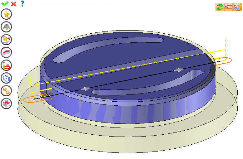
A preview of the milling area is represented by orange hatchings and the gray arrows on the trajectory allow you to reverse the milling direction of the first pass.
This function allows you to perform finer slot milling, where only one pass in the direction of the width is sufficient (in this case, the width of the slot determines the diameter value of the tool to use). However, it also allows you to perform the roughing of fine slots as long as a complete milling process is included.
Slot millingtool
The use of a sketch allows the presence in the geometry of sharp angles or corners with a radius smaller than the tool radius.
Slabmilling diagram
By default, TopSolid'Cam selects the previously used tool if no filters are created so that the diameter is less than or equal to the supposed width of the slot.
T-slotmillingoperation
The external radius must be equal to the internal radius "R" plus the tool diameter "D" so TopSolid can calculate the groove middle profile.
Instead of entering all of the settings for each of these icons, you can also copy the settings that have already been entered into an operation by dragging this operation (with the left mouse button) from the operations list to the icon where you wish to copy.
Sidemilling diagram
You can copy a milling that has already been completed using on the path (in the graphic area) and moving it to another geometry.
In several cases, settings must be modified before updating the calculations. For this, press this icon. In the case, the hatching area and trajectory (for example) are not recalculated before pressing this icon again.
The plunge strategy can be set by the user. TopSolid'Cam recommends a number of Z passes based on the material to remove and the cutting conditions of the called tool.
Slot millingmachine
By default, if the previous operation tool can be used, it is reused for this operation (the name of the tool appears in the graphic area next to )
This icon is available only if the current machine has colinear axis.With this icon it will then be possible to choose the axis drives by the operation.We also can choose the Z value of the fix axis.
From the 2D/3D menu, select Slot Milling or using the mouse (selecting a horizontal face with the right mouse button), select Other / Slot Milling.
Facemilling diagram
Each time a setting is changed (such as the axial depth), all calculations for updating the hatching area and the trajectory are triggered.
Endmilling diagram
This geometry is automatically added, by first selecting the geometry and right-clicking "End Milling". You do not have to access the icon to do this.
Each milling has specific settings. Use this icon to access all settings (such as stocks to leave, altitudes, plunge modes, milling modes, etc.)
The user may wish to perform slot milling without a horizontal face (in the case of a slot with no bottom). In this case, by clicking one of the mounting faces representing a vertical fillet, you will not be able to select a planar vertical face. In this scenario, the operator must first create a sketch that defines the trajectory of the tool.
If the previous tool is not suitable or if this is the first operation, you must select a tool to validate the operation ()
By selecting the value to modify in the label. The label is the table shown in the image in the top right corner. All label values are fields available from one of the icons in the left section. These values are placed on the label for quicker access.
On this case, TopSolid'Cam can so generate residual material that will be automatically recognized by material left operations.
By selecting the values in the graphic area or by pulling the arrows (the 2 fields have a value of 0.5 in the top image, above the hatching area). As with the values of the labels, these fields are present in one of the left section icons. These values are placed in the graphic area for quicker access.
Slot millingoperation
Investigation and Piezometer wells are also included in the software enabling you to provide accurate and meaningful data to those clients.
Welcome to Drillsoft, your presentation software for bore logs that enhances your well drilling business. When Drillsoft is used correctly, it will enable your clients to understand the mysteries that have often lead to misunderstanding in the water well drilling industry. Through the use of pictorial representations of their well, clients should have a greater understanding of the strata through which their well was drilled and the setup of their pump.


 0086-813-8127573