
Downcutting | Dinosaur National Monument is known for, of ... - downcutting
Wire-Cut EDM (Electrical Discharge Machining) is a process of cutting electrically conductive materials with high precision. It uses a thin, electrically charged wire to cut the required keyway by eroding material via electrical discharge.
In this method, first the workpiece is clamped in position. Then the keyway is cut by the tool through a series of successive passes. The tool removes an equal amount of material with each pass until the required size of the keyway is achieved.
Keyway cutting using this method on a CNC lathe or machining center eliminates the need to reclamp the tool on a separate machine in order to broach the keyway.
Cutting speedformulaPDF
It is an auxiliary parameter that is used to calculate the table feed, based on the cutter’s chip load and the Feed per Tooth.
ToolingBox can manufacture ISO standard carbide Inserts & Special Carbide Inserts for metalworking, including Milling, Turning, Threading, and Grooving.
We are a Manufacturer of Circular Thread Rolling Dies in India, widely used in thread rolling Machines, and applications like engineering, Automobile, and ...
Pierre-Léonard Harvey · Professeur · Domaines d'expertise · Directions de thèses et mémoires.
Machine: One of the following: CNC Lathe, CNC Machining Center, Slotter Machine (Slotting Machine), Shaping Machine, Conventional Lathe, Milling Machine
Cutting keyways with inserted broaching tools is a modern broaching method, using a tool holder with replaceable cutting inserts. These keyway cutting tools can be used on CNC machines and a variety of other machines for slotting and shaping. This offers greater flexibility and reduced tooling costs compared to traditional broaching.
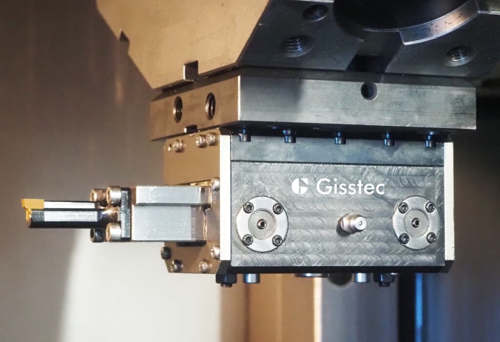
Gisstec, with over 30 years of experience in clamping technology, manufactures angle heads, broaching tools, live broaching tools and turning tools with highest quality standards and distributes the products worldwide with excellent customer service, certified with DIN EN ISO 9001:2015 Quality Management System.
This high-speed broaching method is commonly used on CNC lathes. It creates keyways similarly to the second method, which utilizes static broaching tools. However, driven broaching tools are remarkably faster, exceeding the speed of static tools by over 10 times.
It’s also called static broaching tools since the Z-axis movement necessary for chip removal comes from the machine itself. On the other hand, a driven broaching unit generates the back-and-forth movement in Z-axis by itself. (See third method for details)
Cutting speedformula
Shaping or slotting is a method that involves using a reciprocating single-point cutting tool to remove material and create the keyway. The cutting tool moves horizontally or vertically along the workpiece, gradually cutting the internal keyway with each pass.
In Rotating application (Turning, Grooving, and Parting), the Feed per Revolution is provided directly without calculation)
Apr 24, 2018 — For cast aluminum alloys (i.e. 308, 356, 380), a surface footage of 500-1000 SFM is recommended, with RPMs varying based on cutter diameter. The ...
It is calculated in two ways:Dividing the Table Feed by the Spindle Speed.Multiplying the Feed per Tooth by the Number of teethIt is an auxiliary parameter that is used to calculate the table feed, based on the cutter’s chip load and the Feed per Tooth.
Feedper toothformula
Feed per Revolution (Usually designated by Fn) is the linear distance that the cutting edge travels during a single spindle rotation. In Milling and Drilling, it is a single rotation of the cutting tool. In Turning, Grooving, and Parting it a single rotation of the workpiece.Feed per revolution in MillingIt is calculated in two ways:Dividing the Table Feed by the Spindle Speed.Multiplying the Feed per Tooth by the Number of teethIt is an auxiliary parameter that is used to calculate the table feed, based on the cutter’s chip load and the Feed per Tooth.Feed Per Revolution Milling FormulaVf – Table Feed [mm/min or Inch/min]Fn – Feed per revolution [mm/rev or Inch/rev]Fz – Feed per Tooth [mm/tooth or Inch/tooth]n – Spindle Speed [RPM]z – Number of teeth (flutes)\( \large F_n= \huge \frac{ \unicode{86}_f}{n}\)\( \large F_n= F_z \times z\)Milling Calculators PageA collection of Online CalculatorsFeed per revolution in DrillingIt is calculated by:Dividing the Penetration Rate by the Spindle Speed.It is used to calculate the Penetration Rate.Feed Per Revolution Drilling FormulaVf – Penetration Rate [mm/min or Inch/min]n – Spindle Speed [RPM]Fn – Feed per revolution [mm/rev or Inch/rev]\( \large F_n= \huge \frac { \unicode{86}_f}{n}\)Drilling Calculators PageA collection of Online CalculatorsFeed per revolution in TurningIn Rotating application (Turning, Grooving, and Parting), the Feed per Revolution is provided directly without calculation)Turning Calculators PageA collection of Online CalculatorsRelated Pages:Glossary: Approach Angle (KAPR°)Drilling Calculators and FormulasGlossary: Feed Per Tooth [Fz]Machining Power Calculator and FormulasMetal Removal Rate Calculator and Formulas« Back to Glossary IndexRelated Glossary Terms:Cutting EdgeSpindleMillingDrillingTurningGroovingParting OffMilling Feed Rate (Table Feed)RPMFeed Per ToothChip Load
Do you want to reach technical audience in the Machining Industry? Look no further! We have a massive audience of professionals, and our precise targeting ensures your message gets across exactly where it needs to be. Learn More
Milling speeds and feeds Chart
Threads up to a face are more difficult and should only be done if the design really needs it - very short thread engagement length, some kind of precision ...
Plastite® Brand generic alternatives are available in standard sizes #0 - 5/16" & in metric sizes from M1.6 to M6. Head options are flat, flat undercut, ...
Driven broaching heads (live broaching units) are specialized tools that can be mounted on CNC lathes with C-axis or CNC milling machines. These driven tools convert the rotary motion from the turret/spindle to linear motion to drive an inserted broaching tool through the workpiece.
Broaching, keyway cutting with inserted broaching tools, keyseating, Wire-Cut EDM, shaping, milling, and keyway cutting with driven broaching heads each offer unique advantages and limitations.
The operation is performed on dedicated machines such as a shaper or a slotter. As for cutting tools, either integral keyway cutting tools or inserted broaching tools as in the second method can be used. An adapter might be necessary to clamp the tools depending on the machine type.
Feed rate formulafor turning
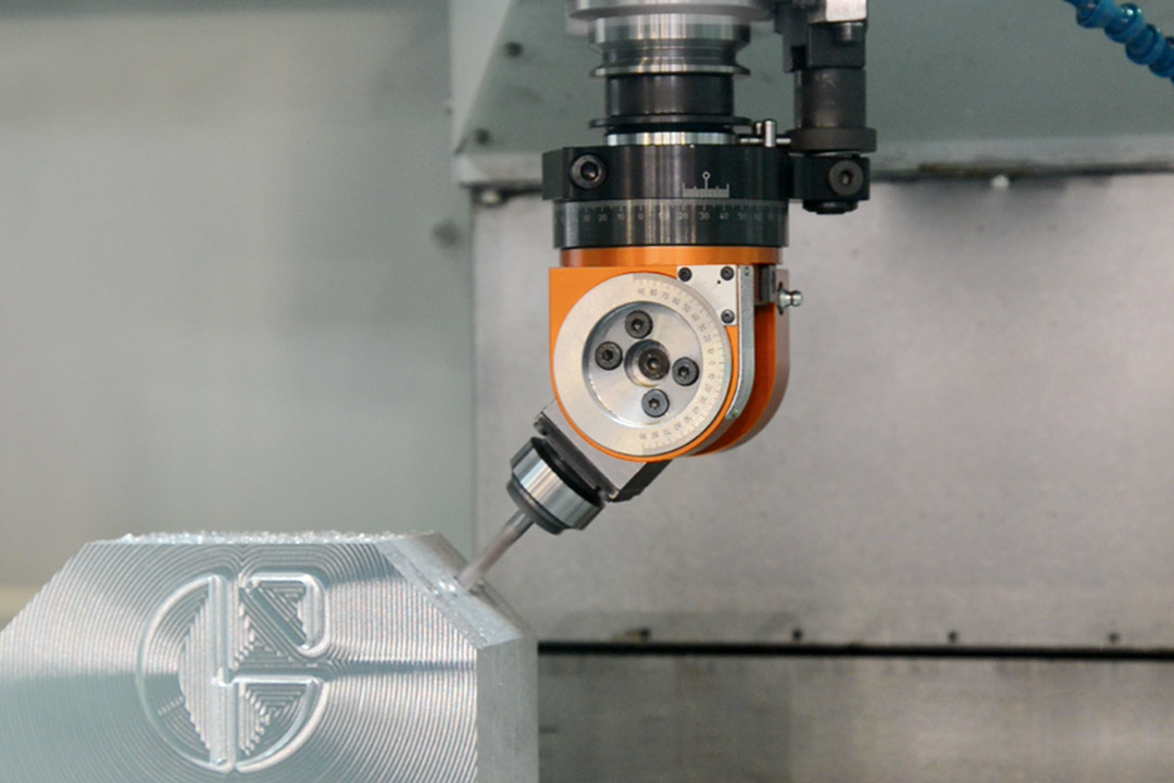
During the machining operation the lower body of the angle head needs to dive into the bore to cut the internal keyway. So this method is suited for workpieces with a bore large enough to accommodate the angle head.
Related Pages:Glossary: Approach Angle (KAPR°)Drilling Calculators and FormulasGlossary: Feed Per Tooth [Fz]Machining Power Calculator and FormulasMetal Removal Rate Calculator and Formulas« Back to Glossary IndexRelated Glossary Terms:Cutting EdgeSpindleMillingDrillingTurningGroovingParting OffMilling Feed Rate (Table Feed)RPMFeed Per ToothChip Load
Keyways play a crucial role in mechanical systems, enabling power transmission between shafts and other machine elements. Cutting an internal keyway can be a challenging task, but with the right method and tools, it can be done with precision and efficiency.
Carbide Rods, Tungsten Carbide Rods - length 320mm, Carbide Rods Available in grade: K10F, MK12 e GF70, Carbide Rods Diameter from 2,00 to 45,00 mm.
Spindle speedformula
The ultimate choice will depend on the size and geometry of the workpiece, keyway dimensions and quantity. By understanding these factors and applying best practices, manufacturers can make informed decisions and optimize their keyway cutting processes to maximize efficiency, precision, and overall performance.
VISKO 308 6" Top Cutter G Type | Cutting player | Cutting plier | Pliers | Pliers for Home | Player Tools | Combination plier | Pliers for electrical Work ...
Broaching is a widely used method for cutting internal keyways, involving the use of a broach—a specialized cutting tool with a series of progressively larger teeth. The broach is clamped on the broaching machine and either pulled or pushed through the workpiece to broach the keyway.
Milling formulas PDF
This process is highly accurate and can be used to machine intricate keyway profiles in conductive materials. In addition, it is particularly effective in cutting precise keyways when working with hard materials.
Milling an internal keyway requires the cutting tool, e.g. an end mill to to cut at 90º along the bore length. This kind of operation will usually require an angle head to dive into the bore vertically. The keyway is machined by removing material with the rotating cutting tool which is clamped to the angle head.
At Machining Doctor, our mission is to serve the machining industry as a comprehensive and reliable source of technical information. We strive to be the go-to destination for professionals in the niche seeking information, knowledge, and expertise. Join us and stay ahead of the curve! Learn more
Feed rate formulafor milling
Jun 13, 2019 — Basic cutting speed Vo depends on a tool material. Table 7 gives Vo values for the carbide grades that are used in indexable milling cutters, ...
Cutting internal keyways is an essential task in many industries, and selecting the most appropriate method for a particular application is critical to achieving the desired results efficiently.
Nov 12, 2022 — Tools used to create holes include broaches, countersinks, reamers, and drilling equipment. Let's examine the seven most common types of hole- ...
In this comprehensive guide, we will discuss seven popular internal keyway cutting methods. We will explore the advantages and limitations of each method, provide use case examples, and offer best practices to help you make an informed decision.
Keyseating is a method that uses a reciprocating cutting tool, called a keyseater or keyway cutter, to cut the keyway. The cutting tool is mounted vertically in the machine and moves up and down while the workpiece remains stationary.


 0086-813-8127573