
Drill & Boring Tools - Series 59 - boring tool for drill
It plays a crucial role in chip formation, tool life, cutting forces, and surface finish. Understanding the influence of the relief angle and selecting the appropriate one can greatly enhance machining performance, productivity, and the quality of the finished product.
A: In machining and other relevant processes, the hardness of the material is a crucial determinant of the cutting speed to be utilized, and in this case, it dramatically influences the cutting speed of aluminum. In most cases, softer aluminum alloys have a more significant diametric cut when compared to the more complex alloys, which have smaller cut diameters; hence, their speed requirements are different during machining processes. It is also paramount to note that the machined alloy should be considered, as this will affect the cutting speed needed for better outcomes.
Carbideinsert Identification
Marketing cookies are used by third-party advertisers or publishers to display personalized ads. They do this by tracking visitors across websites.
Kennametal turninginsert IdentificationSystem
We need your consent before you can continue on our website.If you are under 16 and wish to give consent to optional services, you must ask your legal guardians for permission.We use cookies and other technologies on our website. Some of them are essential, while others help us to improve this website and your experience.Personal data may be processed (e.g. IP addresses), for example for personalized ads and content or ad and content measurement.You can find more information about the use of your data in ourprivacy policy.
There are several ways to control the tool deflection during the cutting process when machining aluminum. This material is required to provide a very high resistance against deformation while being cut. Deflection can be reduced using shorter and more rigid tools since they have lesser chances of bending or twisting under loads. Furthermore, it is essential to use correct geometries and materials, i.e., carbide or high-speed steel cutting tools for aluminum, which can withstand considerable deformation forces. Adjusting feed rates and depth of cut accordingly is vital, along with restricting them at parameters that impose minimum side thrust on the tool. The cutting forces can be enhanced using sophisticated simulation software packages to obtain results by eliminating displacements while performing the cuts under various conditions. In addition, supporting devices like tool holders with high rigidity improvement enable stable machining operations. Equipment should be regularly serviced and inspected to maintain the required alignments to achieve the desired production standard.
All turning inserts have a unique ISO code that contains various letters and numbers – believe it or not, these actually mean something! From just looking at the ISO code you can figure out the insert’s shape, relief angle, tolerance, cross-section type, cutting-edge length, thickness, radius, and chip breaker!
If you are under 16 and wish to give consent to optional services, you must ask your legal guardians for permission.We use cookies and other technologies on our website. Some of them are essential, while others help us to improve this website and your experience.Personal data may be processed (e.g. IP addresses), for example for personalized ads and content or ad and content measurement.You can find more information about the use of your data in ourprivacy policy.Here you will find an overview of all cookies used. You can give your consent to whole categories or display further information and select certain cookies.
Insertnose radius chart
Several core integrities govern your operations when you are looking to achieve maximum material removal with faster CNC machining center metallurgic milling of aluminum. First of all, mention the proper cutting tools. High-speed cutting requires tools with coatings aimed at reducing friction and heat resistance. Moreover, unlike our argument, I maintain perfect synchrony between spindle speed and feed rate to prevent tool wear while enhancing chip clarity. I equally consider how stable the machine operates and the level of vibrations to avoid the scorching issue of weather and resist the optimized features. The factors will be congenial, enabling the tool to target the workpiece efficiently. I employ strategies to use cutting-edge technology while thinking through the machine’s correct performance parameters to deliver optimal CNC machining.
Tolerance dimensions are indicated by a letter ranging from A - U. Dimension A relates to the inscribed circle (IC), dimension B relates to the insert height (for pentagon, triangle, and trigon shapes – for other polygons, the dimension B relates to the distance that is measured along the bisector of the corner angle) and dimension T relates to the thickness of the insert.
Turninginsert Identificationchart
Cutting Speeds for milling aluminum via CNC tend to vary between 800 to 2500 meters per minute depending on the aluminum alloy being used and the type of machining required, irrespective of the properties of the aluminum. The amount of material removed is generally defined as between 0.001 and 0.010 inches per tooth. Modifying some of these factors is essential based on the type of aluminum involved, the cutting tool’s design, and the intended surface quality. High productivity is now possible due to high-speed machining systems; however, there is a need to manage cooling, chip evacuation, and tool wear to ensure the productivity level is not compromised.
Aluminum is a material that interacts with both feed rate and cutting speed. Therefore, it is essential to relate the two while machining this metal. Feed rate, which presents the travel distance of the cutting tool during one spindle revolution, is another of the more damaging parameters that affect tool life, surface finish, and productivity of the machining process. These rates are also affected by other factors like the tool’s shape, the geometric parameters of each operation, and the machining material. It is known that with a proper combination of feed and speed, the maximum material removal rate is achieved with the most minor wear of the cutting tool. These parameters could also be adjusted employing recommendations from tool manufacturers and some tests conducted on the materials having the respective components machined. Consider the machine’s capacity and rigidity; otherwise, vibrations may cause defects in the finished product.
A: Although aluminum can be cut at high speeds, if these are taken to the extreme, it can result in several problems, such as 1. tool breakage, 2. rough finish of the surface, 3. enlarging the edge of the blade, 4. high-temperature production, 5. poor-fitting 6. The workpiece may break. When overall cutting speeds are set for aluminum work, one must compromise tool production lifespan and productivity.
Choosing the right insert shape for your turning tool is essential. The shape of the insert can affect the vibration during operation, the ability to turn complex contours, the strength of the insert and its ability to take bigger and heavier cuts.
The relief angle for a milling insert is of paramount importance in achieving efficient and successful machining operations.
A: The carbide end mill is the best and most preferred end mill for aluminum cutting at high speeds. It offers excellent wear resistance and can retain its edge for long due to high temperatures. Look for end mills explicitly designed for cutting aluminum, as they will have better performance, such as polished flutes that reduce friction and enable better chip removal.
Approaching the characteristics of CNC milling of aluminum, it’s important to consider the specific type of aluminum alloy being machined since different alloy types are characterized by their different mechanical properties, which affect the optimal cutting speed. Further factors are the tool material and coating, which influence wear resistance and heat dissipation. Besides, the strength and the total output capability of the CNC machine determine the maximum speed that a cutting tool can achieve. The type and the way a coolant is applied can also affect the temperature control and surface quality. Finally, the chip load, or the volume of material displaced per cutting edge, should be considered when determining optimum milling speeds to improve the machine and tool’s lifespan.
Turninginsertcode system
In this blog, we will discuss how to identify all these key dimensions, so you will never need to check for part numbers again.
Accept all Save Accept only essential cookies
A: Aluminum requires higher cutting speeds than steel and other more rigid materials. This is because aluminum is softer, and the cutting force due to the cutting tool is minimal compared to cutting more complex materials like steel. Machining aluminum parts can be done at a cutting speed of 5-10 times higher than steel, contributing to high material removal rates during machining.
Both feed rate and spindle speed influence the efficiency and quality of the cutting process. Spindle speed (RPM) also involves the cutting tool’s rotation speed at its working edge, affecting the heat generated and the surface finish achieved. It is critical to know what comprises an optimal ratio since too fast cutting may overheat the tool and cause wear, while too low cutting speeds may degrade the surface and lead to prolonged equipment usage. Feed rate, the per-revolution advance distance for the tool, affects the chip load, which, in turn, affects torque and cutting forces. Feeding spindle speed and feed rates in appropriate amounts makes the operable interface, increases the life of the cutting tool, and improves product accuracy and the latter quality. Nevertheless, these factors should be altered by the features of the material being machined as well as the specifications of the machine, for example, in the case of aluminum machining, which is often required.
Statistics cookies collect information anonymously. This information helps us to understand how our visitors use our website.
When putting coolant to every possible use to enhance surface texture while CNC machining aluminum alloys, the proper choice, and application of the coolant is crucial; it may be accepted as a rule that high-pressure coolant systems are generally beneficial as they improve cooling and chip removal so that the chances of re-cutting of chips and tool marks are minimized. Water-based coolant is used since it can cool the cutting tools and the workpiece and reduce friction, contributing to better surface roughness. Eliminating overheating due to the constant flow of cutting fluid onto the workpiece contributes to the uniform temperature distribution and minimizes thermal distortion, which invariably results in improved surface quality. The composition and concentration of the coolant should also be regularly checked and topped if necessary to ensure the cooling process remains effective and to avoid any contamination that could adversely affect the surface quality.
Carbideinsert identificationchart PDF
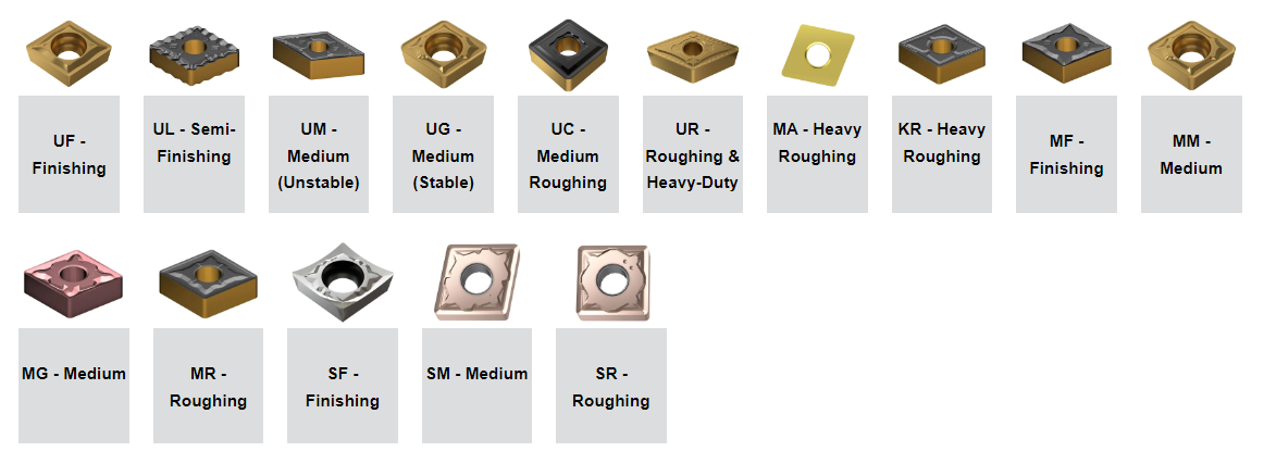
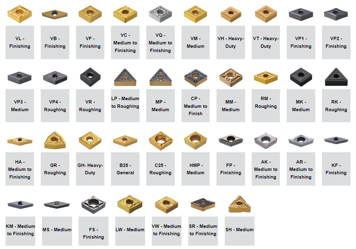
The chip breaker is represented as 2 letters in the ISO code. The chip breaker affects the cutting resistance, if the cutting resistance is low, it can avoid chipping and fracturing of the cutting edges. Reduced cutting resistance can also decrease the tool load and heat built up. The chip breaker also determines the depth of cut the insert can take, if you are not applying the correct depth of cut then you won’t be activating the chip breaker, this can cause the swarf to build up and become stringy, some people refer to this as a bird’s nest.
The analysis of cutting speed for aluminum concerning the tool life and rigidity can be achieved by reviewing the cutting process dynamics. Tool life is a factor of operational efficiency; these tools, which can operate long without changing them, suffer less from downtime. However, considering tool and setup rigidity limits the cutting speeds that can be achieved and even the surface quality. High rigidity results in less vibration and deflection, leading to more stable cutting and, possibly, increased speeds with the exact precision requirements. Designing the tool of appropriate edge geometry to meet the optimal spindle speed and feeding rate gives the best cutting speed for aluminum. Also, newer tool coatings and geometries are still increasing performance by effectively providing appropriate wear resistance and thermal stability necessary for aluminum milling processes.
The thickness of a turning insert is measured from the bottom of the insert to the top of the cutting edge. This will be shown as a 2-digit number except where the insert features a T and then a single digit number eg T3. This is due to the fact that there are more than one increment within each mm. eg 03 is 3.18mm whereas T3 is thickest at 3.97mm.
When milling aluminum, the choice of cutter is critical, considering the product’s quality and the efficiency of the operations. HSS end mills, carbide end mills, and diamond-coated tools are commonly recommended. High-speed steel end mills are cheap and reasonable for regular milling jobs. However, carbide blades are more desirable because of their increased hardness and heat resistance, allowing for higher speeds and longer life. Because of its high wear resistance, diamond-coated tools can be used for high-range specialized applications to maximize tool lification and finish quality. It is essential to select the cutting tool that is appropriate to the particular application and material characteristics.
When selecting an appropriate cutting tool for aluminum components, the features of the cutting tool and the material properties are critical. The number of flutes contributes to the chip removal process and the surface finish; in the case of aluminum, the tools with two or three flutes are used since they minimize both effective material removal and the clearing of chips. Reducing the number of flutes increases the chip load and removal rates, which is essential for soft aluminum. On the contrary, carbide inserts have high hardness and better wear resistance over high-speed steel inserts and are helpful in high-speed cutting. The inserts’ geometrical features can be cut at higher temperatures, which extends their functional performance. When looking for alternatives to these tools, one must consider the specific cutting conditions and the parameters that must be fulfilled to make the best choice.
Deepening the depth of cut on aluminum alloys while CNC milling features various considerations that ensure the cut is optimal. What comes to the advantage here is that every kind of alloy has its recommended cutting depth, which is unique to it; for the more complex alloys, it is recommended they leave more minor cuts to avoid any harm or more significant damage to the tool. It is widely acknowledged among engineering practitioners that a depth of cut between 0.020 and 0.200 inches is ideal, considering the machine configuration and the tool geometry. In addition, there is a chance that deeper cuts could be taken with softer aluminum alloys, which might be the case, provided the cooling and lubrication systems can cope with the added heat and chips created by deep cuts. In the end, however, depth is a compromise between removing as much material as possible, extending work longevity, and maintaining a good surface finish.
Content from video platforms and social media platforms is blocked by default. If External Media cookies are accepted, access to those contents no longer requires manual consent.
I consider some of the best practices recommended by the allied sector references to optimize the cutting conditions and prolong the old life. Firstly, it is important to keep applying the cutting fluid constantly and appropriately, as it helps calm and lubricate the tool, reducing its wear and tear over time. Secondly, in the case of cutting tools, it is very critical to use the appropriate tool material and coating tailored to the material being cut to enhance the respective cutting tools’ response and life. Moreover, as part of my work, I reorder machining parameters like feed rate and spindle speed that fall outside the recommended levels. Doing so helps in lowering the amount of tool stress and improving efficiency. Last, attention to tool wear and replacing them in time is essential for preventing unplanned downtimes and cutting process shifts. If I observe these guidelines, I can guarantee an increased cutting tool life and the ideal operating standards.
For insert shapes such as round, square, triangle & trigon, this would then indicate the diameter of the inscribed circle (IC).
Analysis of the rates and outputs of high-speed steel (HSS) tooling in coordination with carbide tools during CNC milling requires an acute understanding of some factors necessary for maximum optimization. Due to their toughness, HSS tools are more durable and slower than carbide tools. With these characteristics, there is always a cost for something; in this case, HSS tools have a higher wear rate and require frequent maintenance. Carbide tools, on the other hand, can withstand extreme temperatures, allowing for increased cutting and tool life, ultimately increasing SFM and feeds. Carbide tools can withstand 300-1000 or even more SFM, going hand in hand with the suitable aluminum alloy. However, softer metals will allow for an SFM between 30-100. The criteria for selecting a proper feed rate is crucial as it determines the tool’s life without compromising cutting effectiveness. So, a final comparison between FKSS and carbide tools must consider the parts and machining requirements that require these tools.
The cross-section highlights the differences in the design of the insert, such as the fixing holes, countersinks, and special features. This dictates what clamping method would be used to fix the insert on to the tool holder.
A: Numerous parameters determine the ideal cutting speed for aluminum; these include the particular alloy of aluminum to be worked on, the type of end mill or other cutting devices used, the surface texture required, the amount of chips removal needed, and the kind of CNC milling machine to utilize. Furthermore, the use of coating systems on tools when cutting conditions of aluminum and the injection of coolant on the tools, though defined by several parameters, also affect the optimum cutting speed required for cutting aluminum.
A: Typically, the best surface-cutting speed for aluminum lies around 500-1000 SFM. This speed relates to the motion of the tool’s cutting edge during the workpiece’s machining. However, this range may be modified since the hardness of the different aluminum alloys tends to vary.
Some of the below chipbreakers are available on both negative and positive inserts but the min-max depths of cut may vary.

In the ever-evolving landscape of CNC machining, precision and productivity in material removal are arguably the most critical elements in the production process. In this blog, determining the cutting speed of aluminum, which is one of the most used metals by industries due to its strength-to-weight ratio and machinability, is made more accessible. It is well known that optimizing the cutting speed is essential for tool performance, tool life, and the quality of the workpiece. In this article, we shall examine the technical considerations, the computation, and the determinants of cutting speeds, thereby giving readers a broad view of success in the CNC machining of aluminum.
Every metal possesses specific fundamental differences in its physical and mechanical properties. Aluminum, for instance, is much less dense and markedly softer than steel, which allows for short machining cycles with reduced cutting tool wear. It has good thermal conductivity and a lower melting point, enabling it to withstand more heat and increasing the speed of machining operations. Compared to steel, which is less demanding in rigidity and tensile strength, aluminum does not require heavy, complex tooling and cutting engines. Compared to aluminum and steel, aluminum allows for further deformation, but steel is more suitable for applications requiring tremendous strength. All in all, one would have to adjust the machining techniques and the tools used while machining aluminum to ensure that the production processes are effective and qualitative results are achieved.
Kingsun offers outstanding Precision CNC Milling, CNC Turning, Swiss Turning, 3D Printing Rapid Prototyping services for the automotive and medical industries. Also, providing cost-effective high-quality custom services. Make your product work by collaborating with Kingsun!
In the operated division, the utmost cutting velocity is a function of the alloy form, the hardness of the material, the particular machining operation, and the sort of cutting tool. Cutting tools, however, have to meet warranting conditions that do not allow more incredible work speeds than the upper limit. Aluminum alloys can thus be worked at 1500 to 5000 fpm, which is beneficial information when selecting cutting tools. Varying parameters can affect these ranges, such as the cooling system used and the machine operated. Higher-speed cutting is possible because of high wear-resistant carbide tools. It is essential to follow the steel manufacturer’s recommendations and make test samples with realistic conditions to achieve maximum speed-cutting pressure while maintaining the integrity of the modeled objects.
Each member brings with them their own experience and know-how to add to our growing pool of technical knowledge. That’s why our services are known for being the best in the business!
In CNC milling, specific aluminum materials can be used. Still, for any of them, one must consider aluminum’s material properties, as top industry experts explain. The typical aluminum alloys used in CNC milling include 6061, 6063, and 7075 as their machining characteristics and performance. Every alloy requires special cutting tools and lubrication methods to minimize tool usage and maximize surface finish. In addition, factors like build-up edge and chip removal are conducive to maintaining aluminum’s low density and thermal conductivity, which also calls for maintaining suitable feed rates and spindle speeds. Using aluminum machining technology tools made of high-speed steel or carbide would speed up the process and increase the tools’ durability. Furthermore, Alloys would only require some coolant in a timely, thereby averting heat-related deformations while enhancing the precision of the final product.
The nose radius of an insert can affect the performance. A larger nose radius can result in the use of higher feed rates, and larger depths of cut, and they can handle more pressure, making them much better for heavier metal removal. Whereas a turning insert with a smaller nose radius can only take smaller depths of cut, they also have weaker cutting edges, and they can only handle a small amount of vibration but are much better for finishing as they are sharper and have less surface contact.
A: In aluminum milling, the feed rate is almost equal to the cutting speed. Basically, the higher the cutting speed, the higher the feed rate. However, these parameters must be optimized for satisfactory chip formation and evacuation, especially concerning tool selection factors. The general target is between 0.001 and 0.010 inches of chip load (feed per tooth), depending on the conditions of the cut and what the finish is targeting.
It is a 2-digit number that generally indicates the width or length, however this is only applicable to insert shapes with no IC (inscribed circle), such as rectangular and parallelograms.
Statistics cookies collect information anonymously. This information helps us to understand how our visitors use our website.


 0086-813-8127573