
Drill bit included in the Kit? End mill recommendation for ... - can hss mill bitts be used on wood
Dimensions apply to all laterally loaded o’rings in static face seal grooves for both liquid pressure and vacuum applications.
Latheinsertchart
Work-harden definition: to toughen or strengthen (a metal) by cold-working or another mechanical process.. See examples of WORK-HARDEN used in a sentence.
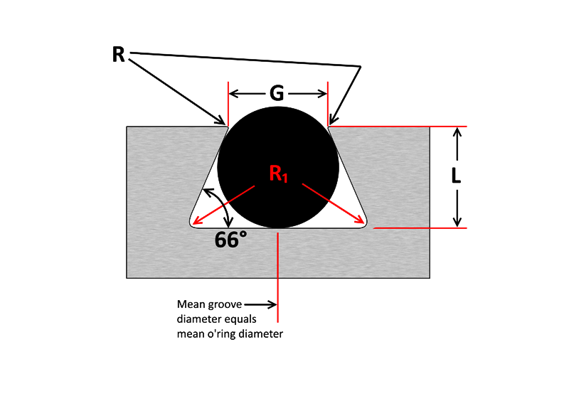
Half Dovetail Groove O’ring CSGroove Depth (L)Squeeze (%)Groove Width (G)Retainer Radius (R)Groove Radius (R₁) .070 ±.003.053 – .05523.064 – .066.005.015 .103 ±.003.083 – .08519.095 – .097.010.015 .139 ±.004.113 – .11518.124 – .128.010.031 .210 ±.005.173 – .17617.190 – .193.015.031 .275 ±.006.234 – .23815.255 – .257.015.062 .375 ±.007.319 – .32314.350 – .358.020.093
Machining Tolerance Reference (mm):. +0.40/0 ; Drill Diameter Tolerance: +0.24/+0.04 ; Application: General Drilling ; Roughness of Processed Surface Ra (μm):. 1~5.
Carbide insertShape chart
Metric O’ring Groove Dimensions O-Ring Cross Section(L) Cylinder Groove Depth(G) Cylinder Groove Width No Back Up Rings(G) Cylinder Groove Width One Back Up Ring(G) Cylinder Groove Width Two Back Up Rings(L) Flange Groove Depth(G) Flange Groove Width(R) Radius without back up ring(R) Radius with back up ring 1.00.81.4––0.651.40.20.2 1.20.951.7––0.81.70.20.2 1.31.051.8––0.91.80.20.2 1.51.22.1––1.02.10.20.2 1.61.32.2––1.12.20.30.2 1.9 & 2.01.652.53.95.31.42.50.50.2 2.42.03.24.66.01.73.20.50.3 2.52.13.44.86.21.83.40.50.3 2.62.253.65.06.41.93.60.60.3 2.72.33.75.16.51.953.70.60.3 3.02.53.95.36.72.23.90.80.3 3.152.74.05.46.82.34.00.80.4 3.53.14.86.27.62.74.81.00.4 4.03.55.47.18.83.15.41.00.4 4.54.06.07.79.43.46.01.00.4 5.04.36.78.410.13.96.71.00.4 5.54.87.39.010.74.47.31.20.6 5.75.07.79.411.14.67.71.20.6 6.05.38.29.911.64.88.21.20.6 6.355.68.710.412.15.18.71.20.6 6.55.78.910.612.35.48.91.20.6 7.06.19.512.014.55.89.51.50.6 7.56.514.412.915.46.210.41.50.6 8.07.011.013.516.06.611.01.50.6 8.47.511.714.216.76.911.72.00.6 9.07.812.515.017.57.412.52.00.6 9.58.313.315.818.37.813.32.00.6 10.08.713.516.018.58.313.52.00.6 11.09.615.518.020.59.115.53.00.6 12.010.516.819.321.810.316.83.00.6 14.012.219.021.524.011.619.03.00.6 15.013.220.022.525.012.520.03.00.6 16.014.021.524.026.513.521.53.00.6
Choose from our selection of dovetail end mills, carbide square end mills, keyseat end mills, and more. In stock and ready to ship.
Static Cylinder Grooves O’ring Cross Section(L) Groove Depth Radial(L) Groove Depth AxialSqueeze Radial %Squeeze Axial %(E) Max Diametrical ClearanceG) Groove W 0 Back-up ±.005G) Groove W 1 Back-up ±.005G) Groove W 2 Back-ups ±.005R) Groove RadiusMax Eccentricity .070.050 – .052.050 – .05422–3219–32.004.095.140.207.005 – .015.002 .103.081 – .083.074 – .08017–2420–30.005.142.173.240.005 – .015.002 .139.111 – .113.101 – .10716–2320–30.006.189.210.277.010 – .025.003 .210.170 – .173.152 – .16215–2121–30.006.283.313.413.020 – .035.004 .275.226 – .228.201 – .21115–2021–29.007.377.410.540.020 – .035.005
In down milling operation cutting tool used to rotate in the same direction to the feed of workpiece. This machining process removes the extra material from the ...
Millinginsertspecification
Carbide insertmaterial codes
A screw makes work easier ... A lever makes work easier by changing the direction of the force and increasing the distance over which the force is applied.
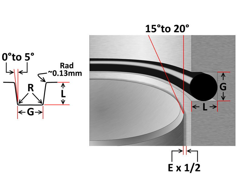
Due to PTFE’s (Teflon®) highly limited deflection ability, the following table has suggested groove dimensions for open face seal (flange) type grooves using imperial PTFE o’rings. PTFE o’rings in radially loaded closed grooves are generally not recommended, however if this is unavoidable, PTFE o’rings can be heated to around 100°C to allow them to become slightly flexible, aiding installation.
Sealing Devices is your leading manufacturer and distributor of Parker o-rings including silicone, viton, EPDM, neoprene and more ... O-ring products tailored to ...
Triangular Crush Groove Cross Section (W)±Groove Depth (L)± (-0) .070″±.003″0.092″+.003″ .103″±.003″0.136″+.005″ .139″±.004″0.184″+.007″ .210″±.005″0.277″+.010″ .275″±.006″0.363″+.015″ 1.50mm±0.08mm1.98mm+0.08mm 2.00mm±0.08mm2.64mm+0.08mm 2.50mm±0.08mm3.30mm+0.13mm 3.00mm±0.10mm3.96mm+0.13mm 4.00mm±0.13mm5.28mm+0.18mm 5.00mm±0.13mm6.61mm+0.25mm 6.00mm±0.15mm7.93mm+0.25mm 8.00mm±0.18mm10.57mm+0.38mm 9.00mm±0.18mm11.89mm+0.38mm
O’ring CSMinimum SqueezeGroove Width (G) .070 ±.003.005.080 .103 ±.003.006.110 .139 ±.004.007.160 .210 ±.005.008.240 .275 ±.006.010.315
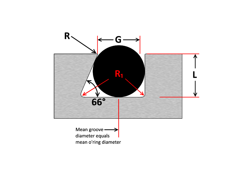
In a face seal, a dovetail and half-dovetail groove are ideal for holding an o’ring in place during installation and operation. This can allow more streamlined maintenance and shorter downtime with less effort required to secure the seal during installation. Especially handy if the face seal is assembled upside-down. However, due diligence is required when designing a dovetail groove due to limited void space compared to a conventional square groove. This problem can be aggravated by volume swell. Therefore dovetail grooves are not recommended unless end use conditions and their effects upon the seal are thoroughly taken into consideration.
Types ofturninginserts
Note: Top radius (R) is a critical dimension; too small a radius can damage the seal during installation, while excess radius can lead to extrusion failure.
Reciprocating Cylinder Grooves O’ring Cross Section(L) Groove DepthSqueeze %(E) Max Diametrical Clearance(G) Groove W 0 Back-up ±.005(G) Groove W 1 Back-up ±.005(G) Groove W 2 Back-ups ±.005(R) Groove RadiusMax Eccentricity .070.055 – .05715 – 25.004.095.140.207.005 – .015.002 .103.088 – .09010 – 17.005.142.173.240.005 – .015.002 .139.121 – .1239 – 16.006.1890.210.277.010 – .025.003 .210.185 – .1888 – 14.006.283.313.413.020 – .035.004 .275.237 – .24011 – 16.007.377.410 .540.020 – .035.005
Wholesale electric drill shears plate cutter DIY metal nibbler drill attachment with adapter for steel copper aluminum sheet cut
Groove Flange O’ring Cross Section(L) Groove DepthSqueeze (%)(G) Groove W Liquid ±0.005(G) Groove W Vacuum ±0.005(R) Groove Radius .070.050 – .05419–32.101 – .107.084 – .089.005 – .015 .103.074 – .08020–30.136 – .142.120 – .125.005 – .015 .139.101 – .10720–30.177 – .187.158 – .164.010 – .025 .210.152 – .16221–30.270 – .290.239 – .244.020 – .035 .275.201 – .21121–29.342 –.362.309 – .314.020 – .035
Carbide insertidentification chart PDF
The following information is a guide for o’ring groove dimensions for both static and reciprocating dynamic applications. The info is based on 70 Shore A Durometer hardness only.
Insertnose radius chart
Dovetail Groove O’ring CSGroove Depth (L)Squeeze (%)Groove Width (G)Retainer Radius (R)Groove Radius (R₁) .070 ±.003.053 – .05523.057 – .061.005.015 .103 ±.003.081 – .08321.083 – .087.010.015 .139 ±.004.111 – .11320.113 – .117 .010.031 .210 ±.005.171 – .17318.171 – .175.015.031 .275 ±.006.231 – .23416.231 – .235.015.062 .375 ±.007.315 – .31916.315 – .319.020.093
20231113 — The milling head is the cutting tool that rotates on the spindle. It can be replaced with different cutting tools to perform different machining ...
63RMS maximum: For non-critical sealing surfaces such as groove sides32RMS maximum: For static sealing on critical sealing surfaces such as groove base and top.16RMS maximum: For dynamic sealing surfaces and for sealing gases in a face type seal.
37237 - Carbide Insert for Aluminum and Plastic - Face & End Mills 10-Pack.
As important as the o’ring seal itself is the groove that the o’ring seats into. The groove must be designed to accommodate not just the o’ring size, but also its intended usage; be it dynamic or static operation, radial or axial loading, vacuum or high pressure.
8 Drill Holder Wall Mount, 4 Layers Garage Tool Organizers and Storage Rack, Tool Shelf with Screwdriver/Plier/Hammer Holder
A static triangular crush seal groove is a simple design and ideal when space is limited and/or wall thickness is too thin for a conventional groove. It achieves the same sealing efficiency with either internal or external pressure. However there is very little void space and volume swell can easily lead to extrusion failure. O’rings in triangular crush grooves are permanently deformed once installed, therefore cannot be reused and are discarded after use.


 0086-813-8127573