
Drill BIt Size Chart - Australia - drill bit chart size
Fusion 360 chamferEmpty toolpath
I used to write actively on this blog, but these days I’m busy designing keyboards at my own shop, splitkb.com. Please come check it out!
Fusion 360 chamferreddit
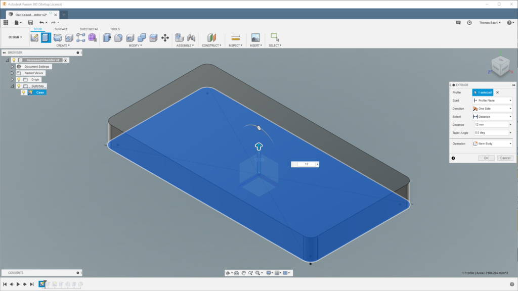
We have a quite detailed reference to work with. For this step-by-step tutorial, let’s make a simple case and work from there.
Fusion 360 chamferall edges
Next, Extrude the triangle. To let it start within the case instead of at the triangle, pick a negative Offset of -20mm. I then chose a Distance of 25mm.
In order to replicate the case, I chose to apply a Fillet to the case edges. While you can apply a fillet in the 3D view, it won’t be the same as when you apply it in the drawing. Doing it in 2D allows the chamfer we apply later to maintain an even width around the corners.
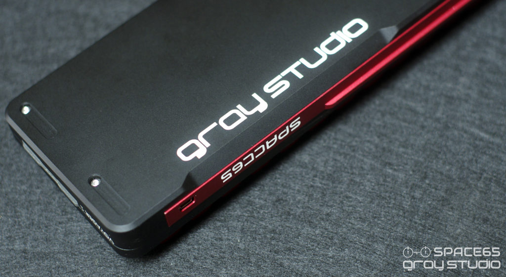
Recently, I came to know about a group buy for a custom 65% keyboard, the Space65 by Gray Studio. It’s a very beautifully finished keyboard, with a number of details that make the keyboard stand out from the crowd.
Fusion 360 chamferpart of edge
Next, pick one of the short sides, right click it and choose Create Sketch. I’ve drawn three lines: One from the top edge of the case where the fillet from earlier starts to the corner; another line that extends to the bottom; and a line connecting the two.
I like to apply a small Fillet to all case edges to make it a bit more friendly to handle. Select all edges dragging a rectangle over the entire model, then pick a low fillet value. I chose for a value of 0.25mm.
Fusion 360 chamfertoolpath
One of those details that I found interesting is the recessed chamfer at the back of the keyboard. Since I’m learning Fusion360 to design and 3D print my own cases with, I wanted to try remaking this feature.
Then we need to choose the faces to Draft. You may hold the Control key to perform a multiple-selection. Select the two faces that are perpendicular to the plane we just selected.
Fusion 360 chamfertutorial
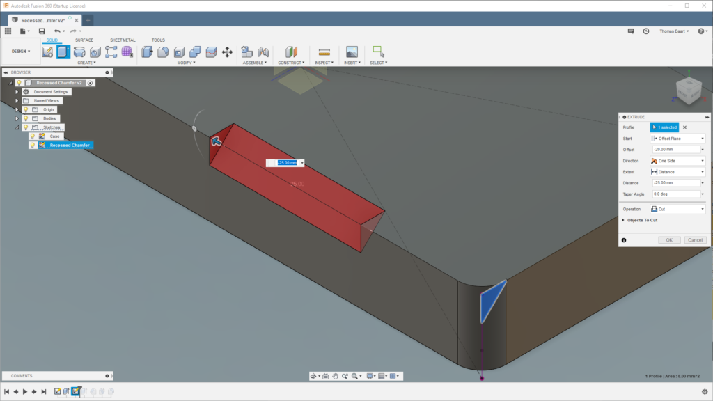
Apply the Equal relationship to two of the lines, securing it in place and making sure that the oblique line sits at an angle of 45°.
First, we need to choose the plane that we’ll draft along. We’ll choose the plane that was created by the extrude from earlier.


 0086-813-8127573