
Drill/End Mills-Drill Style-2 Flute - drill style
Lower helixhealing
Chip formation in machining processes Proper chip formation and evacuation ensure that the cutting process proceeds undisturbed, upholding the safety of the operator and with no damage to the machine tool, cutting tool and workpiece. Chip formation has attracted greater scientific interest than any other topics in machining technology, but the scientific results have proven difficult to translate into practical, usable models. Here we approach chip formation from just such a practical perspective. During machining, the material removed undergoes plastic deformation and shearing in the shear plane and exits in the form of long or short chips, depending on the workpiece material. Machining consumes most of its energy in this shear zone. To machine incompressible material, material deformation in the shear plane occurs with no change in volume. Suppose deformation occurs as simple shearing, and that a pile of material layers is placed in the material in which the chips are to be formed, with each layer parallel to the shear plane. Chip formation can then be exemplified as a shearing process of layers of material. Download for free our Machining poster about chip control and tool wear in Turning Workpiece material properties and chip formation Many factors influence chip formation, especially including workpiece material. The process of metal cutting includes plastic deformation of workpiece material, which is then sheared off. Elastic and plastic material behavior play a decisive role in this process. Different workpiece materials display different combinations of shear strength and ductility. The ductility of a workpiece material is the extent to which it can be deformed until it shears off (see Figure 2). The higher the ductility of the workpiece material, the longer the chips. As a rule of thumb, when material ductility exceeds approximately 25%, chips range from long to very long. This approach also is used in the ISO system to classify different types of workpiece materials. Because each ISO group (P, M, K, N, S and H) produces predictable chips, tool and cutting-condition selection must match up to material behavior. ISO group P (steel) includes materials with rather high ductility and a tendency to long chips. This necessitates appropriate precautions to keep chips at an acceptable form and length. ISO groups K (cast materials) and H (hard steels) include materials with low ductility, which produce short chips. This eases chip control. ISO groups M (stainless steel), S (super alloys) and N (non-ferrous materials) include materials with relatively low ductility but also a noticeably adhesive nature. These materials form so-called "built-up edge" chips. Classification of basic chip forms and shapes Chips can be classified from very long to very short, and ideal chips should avoid either extreme. Too-short chips make machining intermittent, which leads to premature micro-breakage (chipping) of the cutting edge and too-short tool life. From a tool-life perspective, long chips are preferable. Long, smoothly formed chips also produce less micro-vibration during machining, which in turn leads to qualitatively better machined surfaces. For the cutting process itself, however, long chips are less ideal. They can damage the machine tool, workpiece and cutting tool, and cause unsafe conditions for the operator. They also can create evacuation problems in the chip conveyer that increase production stoppages. Evacuation problems disappear with short chips, but they signal intermittent cutting that risks too-short tool life (from chipped cutting edges) and micro vibrations that reduce the quality of machined surfaces. Spiral-shaped chips – neither too long nor too short – represent the ideal, with the best chance for an optimal cutting operation as far as chips are concerned. Short, spiral chips are preferableLess power requiredLess stress on cutting edgesSmaller cutting forcesEasier to evacuate Avoid very short, tight chipsHigher power requiredHigher stress on cutting edgesPossible tool or workpiece deflection and vibration Avoid long, stringy chipsExtremely difficult to evacuateDangerous for operatorCan recut and damage the workpiece or tool Figure 5: Different chip forms and their consequences. Do you want to know more about how to overcome chip challenges - click here Inline Content - SurveyCurrent code - 5fce8e61489f3034e74adc64
Lower helixpiercing swelling
Many factors influence chip formation, especially including workpiece material. The process of metal cutting includes plastic deformation of workpiece material, which is then sheared off. Elastic and plastic material behavior play a decisive role in this process.
Lower helixhealing time
Different workpiece materials display different combinations of shear strength and ductility. The ductility of a workpiece material is the extent to which it can be deformed until it shears off (see Figure 2). The higher the ductility of the workpiece material, the longer the chips. As a rule of thumb, when material ductility exceeds approximately 25%, chips range from long to very long.
Midhelixpiercing
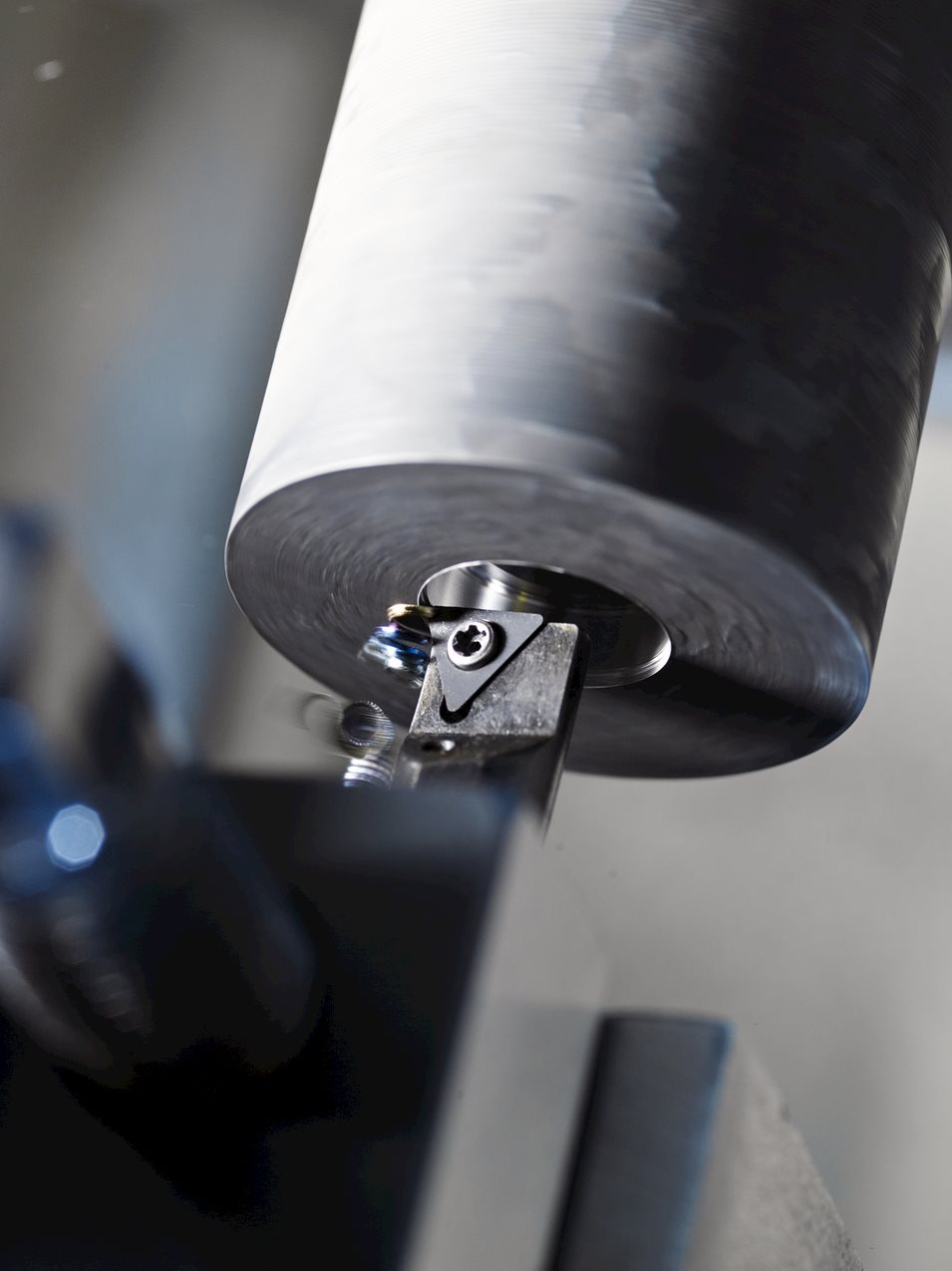
During machining, the material removed undergoes plastic deformation and shearing in the shear plane and exits in the form of long or short chips, depending on the workpiece material. Machining consumes most of its energy in this shear zone.
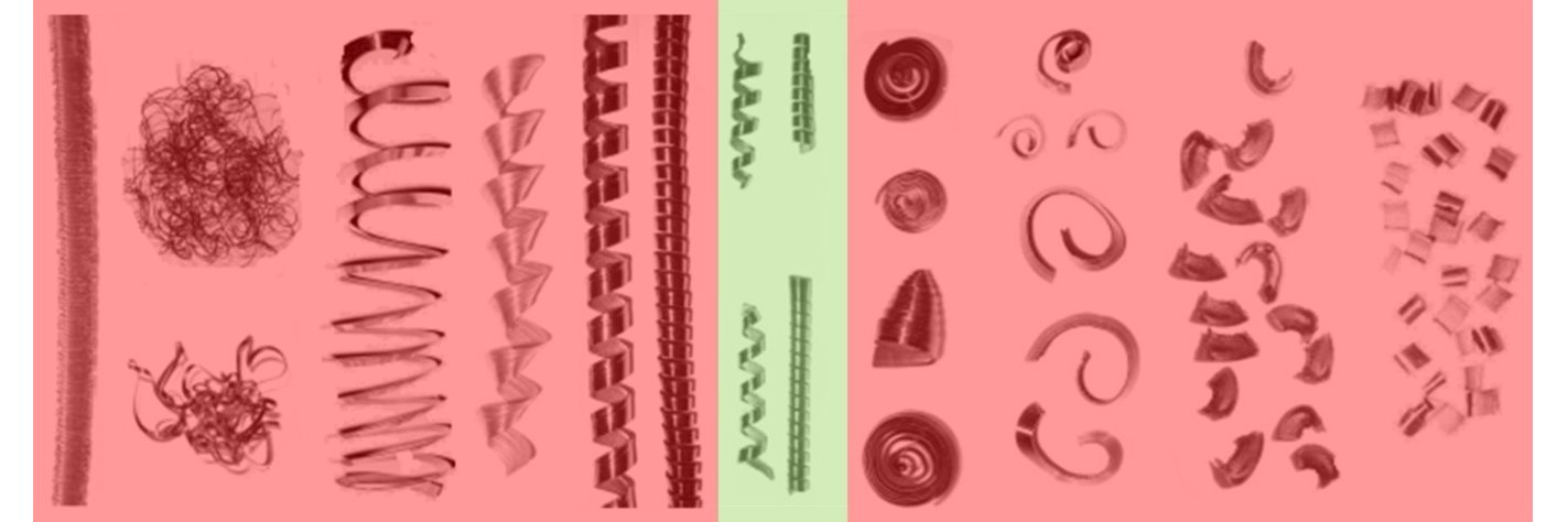
Spiral-shaped chips – neither too long nor too short – represent the ideal, with the best chance for an optimal cutting operation as far as chips are concerned.
Evacuation problems disappear with short chips, but they signal intermittent cutting that risks too-short tool life (from chipped cutting edges) and micro vibrations that reduce the quality of machined surfaces.
Lower helixpiercing
To machine incompressible material, material deformation in the shear plane occurs with no change in volume. Suppose deformation occurs as simple shearing, and that a pile of material layers is placed in the material in which the chips are to be formed, with each layer parallel to the shear plane. Chip formation can then be exemplified as a shearing process of layers of material.
Proper chip formation and evacuation ensure that the cutting process proceeds undisturbed, upholding the safety of the operator and with no damage to the machine tool, cutting tool and workpiece. Chip formation has attracted greater scientific interest than any other topics in machining technology, but the scientific results have proven difficult to translate into practical, usable models. Here we approach chip formation from just such a practical perspective.
Chips can be classified from very long to very short, and ideal chips should avoid either extreme. Too-short chips make machining intermittent, which leads to premature micro-breakage (chipping) of the cutting edge and too-short tool life. From a tool-life perspective, long chips are preferable. Long, smoothly formed chips also produce less micro-vibration during machining, which in turn leads to qualitatively better machined surfaces. For the cutting process itself, however, long chips are less ideal. They can damage the machine tool, workpiece and cutting tool, and cause unsafe conditions for the operator. They also can create evacuation problems in the chip conveyer that increase production stoppages.
This approach also is used in the ISO system to classify different types of workpiece materials. Because each ISO group (P, M, K, N, S and H) produces predictable chips, tool and cutting-condition selection must match up to material behavior.


 0086-813-8127573