
Easy Ways to Lose Weight - truvy tools
Milling was the easy option for me – including workholding which is simples on a versatile vice. So what about feeds/speeds?
On the other hand, the same correlation could not be identified for the drill geometry. In spite of the larger extension of the damaged area, the plates drilled with the twist drill returned higher values of bearing strength, as observed in Figure 2b. This result suggests that the drill geometry is a key factor in damage onset and propagation. So, a good selection of the tool, combined with the feed rate can reduce the damage extension. Nevertheless, one should keep in mind that the existence of damage, such as delamination, around the hole can sometimes act as a stress relief factor increasing the force-carrying capacity of the plate. Therefore, testing results can sometimes be odd when correlating with damage extension caused by diverse drill geometries.
Official websites use .gov A .gov website belongs to an official government organization in the United States.
I forgot I had an ER 32 – R8 chuck! Another tool justified, Hurrah! 5000rpm, carbide stub mill, dry…. smooth like butter (I listen to Kpop in the workshop). And the mill seems to have ‘worn in’ a bit at the 5000rpm now.
Bearing stress test: (a) feed rate effect on the bearing strength; (b) drill geometry influence on the bearing strength.
Zitoune et al. [7] investigated the influence of the machining performance during drilling of sandwiched composites using various dimensions of double cone drill. In the experimental work presented, the authors concluded that it is possible to reduce the thrust force during drilling by using a double cone drill in a multi-material aeronautic component (copper mesh/CFRP laminate/carbon-epoxy fabric layer).
The results of the DCB test are presented in Table 1, and an example of a load-displacement curve can be seen in Figure 1. The values obtained in this test are in accordance with other values found in the published literature [16,17], and were important for the subsequent mechanical testing.
Pipeline of the computational processing of a radiographic image: (a) original image; (b) image segmented by using a neuronal network; (c) identification of the delamination region.
Using a small diameter cutter on an unpredictable metal is high-risk. The cutter might happily plough through before suddenly hitting an occlusion or hard spot, blunting the edge or suddenly increasing the side load to breaking point. Rapid swarf clearance is important, because it adds to side-loading and causes blunting. Only the operator can judge, and I’d expect to break a few cutters before finding a safe optimum. A steady hand is important too – bumping is likely to break a small cutter. (You can guess how I know!)
This hole damage evaluation method is based on the existence of damage images from C-Scan and pixel counting of the digitized damage area, as described in [32], or from digitized radiographs [33]. In spite of the interesting approach of this criterion, it will not be used in this work.
Beware! Cast-iron is frequently nasty, full of occlusions, and/or chilled super-hard by being hosed down in the foundry. Machinability varies from wonderful to very poor depending on what you have. Rule of thumb cutting calculations may not work out in practice because “cast-iron” is pretty random, especially if it was chilled, causing a hard skin of unknown depth. A small diameter cutter could sail through it, or come quickly to grief.
One of the most common problems relates to the need of drilling without delamination. Several studies on this subject have been reported, and it is therefore now possible to envisage a drilling strategy that keeps delamination risk at a minimum. Davim and Reis [4], studied the effect of cutting parameters on specific cutting pressure, delamination and cutting power in carbon fibre reinforced plastics. The authors concluded that feed rate has the greater influence on thrust force, so damage increases with feed. Hocheng and Tsao [5], conducted several practical experiments to support the benefit of using special drills instead of twist drills. In this work, the authors concluded that thrust force varies with drill geometry and with feed rate which allows for the use of higher feed rates if adequate drill geometry is selected. Durão et al. [6], confirmed the influence of appropriate drill geometry selection on delamination reduction, as well as the advantage of the use of a pilot hole strategy.
2-flute HSS use all your 5000rpm but you need a small chipload on a 2mm cutter so around 0.004mm which equates to a feed of 40mm/min which is prossibly slower than the power feed will run at. Cut the full 0.5mm depth in one go and do it dry with air or vac to clear swarf.
The characteristics of carbon fibre reinforced laminates have widened their use from aerospace to domestic appliances, and new possibilities for their usage emerge almost daily. In many of the possible applications, the laminates need to be drilled for assembly purposes. It is known that a drilling process that reduces the drill thrust force can decrease the risk of delamination. In this work, damage assessment methods based on data extracted from radiographic images are compared and correlated with mechanical test results—bearing test and delamination onset test—and analytical models. The results demonstrate the importance of an adequate selection of drilling tools and machining parameters to extend the life cycle of these laminates as a consequence of enhanced reliability.
Shaper – you need a bigger one than I have. Slitting saw – reach is the problem… I’d certainly have to come at it from both ends. It is 30mm thick so I could just clamp it vertical in the vice, but still, not sure reach gets me to the middle.
I have made similar plates which were used to lap the face of levers for aircraft controls. This was before CNC was around. To find hard spots they were surface ground and then laped on a granite surface plate with fine wet and dry paper and hard spots would usualy show up as shiny spots or area’s and discarded. They were eventually cut on a horizontal mill with a slotting saw cutter.
The results from the damage extension related with the tool geometry are shown in Table 2. It should be noted that, to reduce the amount of data presented, Table 1 presents average values for the three feed rates used in the experimental work.
Keywords: fiber reinforced composites, carbon fibers, drilling, thrust force, delamination, radiography, computational image processing and analysis, bearing test
In the experimental work presented in [31], the author examined the effects of tool geometry and cutting parameters as well as of tool wear on the delamination factor. Two types of drills were used: a carbide drill and a HSS drill. The damage zone was evaluated by using radiographic non-destructive inspection, and the results showed a near-linear relationship between the delamination factor and average thrust forces for both drill materials. The author also concluded that the thrust force increased when the drill point angle increases and that the helix angle did not have a significant effect on this force. Also, the tool flank wear causes an increase of the delamination factor, as the thrust force increases with the tool wear.
The authors would like to express their acknowledgment to INEGI for the fabrication of the plates, to the Mechanical Workshop of DEM/ISEP for the drilling work and to the Mechanical Test Laboratory of DEM/ISEP for the mechanical test work.
From these results, it is possible to state that the selection of an appropriate combination of tool geometry in relation to the characteristics of the plate is more important than the tool’s influence. This must always be kept in mind when defining the drilling conditions. Unsurprisingly, the feed rate has to be kept as low as possible, to minimize damage extension. The limit on this condition is given by the need to avoid unwanted thermal damages that result from the matrix softening and the need, in industrial terms, to ensure a reasonable number of hourly productions.
1/ machine cast iron dry and use a gentle air blast to clear swarf. The graphite and chippy nature of CI makes lubrication unnecessary. 2/ calculate the cutting depth of each blade on each revolution – you need to avoid rubbing so your slow feed at high rpm was blunting the cutter. 1 thou min per bite per blade every revolution. 3/ yes a high feed rate will put a lot of sideways strain on the small cutter so you will have to reduce the vertical depth. 4/ a better bet is to make an engraving V cutter as the form is designed for doing lots of thin lines. 5/ without a shaper you can still improvise by mounting the work on the lathe saddle and making a non rotating between centres boring bar to hold the cutter. Or on the mill table and non rotating cutter.
How flat is ‘optically flat’? If you are looking for something that is better than a few fringes, then it is a bit of an art!
Carbide Tipped Corner Round End MIlls .187 .203 .218 .250 .312 .343 .375 .406 .437 .468 .500 .562 .625 Radius ID 1873. Tool Diameter: .9895 Inch, .926 Inch ...
In this case, material is cast-iron so a further correction may be needed. A little complicated because cast-iron is a family of alloys with different cutting properties, not a single standard metal. Generally, I halve RPM when cutting cast iron, so:
The experimental sequence described herein does not correspond to a complete factorial or to a Design of Experiment plan as there were some limitations on the tool availability and number of test coupons. Considering HSS tools, there are no Brad or step tools or other geometry for composites material drilling. This option was to highlight the worst possible case in terms of experimental results and to enable us to demonstrate the consequences for mechanical test results when comparing the results of HSS and WC twist drill. So, the main target is the comparison of three different tool geometries.
Delamination onset test results as a function of uncut thickness (h) and test speed—experimental values and analytical model Equation (1).
Shop Emuge 8mm 2 Flute Carbide Ball Nose XLG (Lollipop) Endmill 1935A.008 at Superior Machine & Tool, a leading distributor of metalworking and MRO products ...
Mehta et al. [32] have suggested a different ratio with the same purpose, named damage ratio, DRAT; defined as the ratio of the hole peripheral damage area, DMAR; to the nominal drilled hole area, AAVG, i.e.,:
For anyone who doesn’t have a compressor or a suitabe vacuum cleeaner I have found blowing down a large diameter drinking straw to be surprisingly effective in clearing swarf if ultimately rather tiring.
Jason recommends cutting full-depth in one go and he is a much more experienced and effective machinist than me. However, another duffer rule of thumb is to cut no more than 20% of cutter diameter deep, which is 0.4mm. Therefore I’d probably cut these grooves in two passes. My 20% rule is conservative though, and not entirely sensible! Although shallow cutting reduces the side-load, taking two passes blunts the cutter extra fast, which increases the side load. The pros and cons aren’t black and white.
How long will the cutter last? Roughly speaking, a lightly loaded HSS cutter machining mild-steel will last a couple of hours before it gets too blunt. Driven hard, fast and deep, perhaps only 15 minutes. Jason’s 40mm per minute feed-rate is about right, so the number of cutters needed can be estimated from the groove lengths, and assuming mid-range life of an hour. Except 2mm diameter cutters are easily broken…
As to the delamination onset test, the results found are presented in Figure 3. These results correspond to the tests carried out using the tungsten carbide twist drill as a punch. As expected, the delamination onset load increases with the uncut thickness, according to analytical models prediction. Regarding the testing speed, there was a large scattering of the results when using the lowest speed: 1 mm/min. Finally, the experimental work was focused on the two remaining speeds: 3 and 6 mm/min, so more specimens were tested under these two speeds. It seems, from the results presented herein, that the delamination onset load tends to decrease as testing speed increases. This aspect of the testing speed will need further attention as the lower feed rates used in drilling, around 0.01 mm/rev, would correspond to a testing speed of 14 mm/min in a 1400 rpm spindle speed machine, but without the cutting action promoted by the rotating movement of the tool. There is no doubt that it is important to establish a range of acceptable testing speeds to enhance and strengthen the conclusions from this experimental technique.
After the drilling process, the delaminated region around each drilled hole was evaluated using enhanced digital radiography. To generate a suitable image contrast, the plates were first immersed in di-iodomethane for approximately 15 to 20 min. Then the radiographic images were acquired using a 60 kV, 300 kHz Kodak 2100 X-Ray system associated with a Kodak RVG 5100 digital acquisition system (Kodak Corp., Rochester, NY, USA). The exposition time was set to 0.125 s.
Taking the main problematic issues related to laminate parts into account, it is possible to find different arguments for the selection of conventional materials. One of them is associated with the relative complexity and cost of the production process. In the later stage of parts production, machining operations like drilling are frequently needed in composite structures, as the use of bolts, rivets or screws is required to join the parts. Generally, machined parts have poor surface appearance and tool wear is higher. One of the problems related with composites’ machining is the nature of the fibre reinforcement, which is usually very abrasive and causes rapid tool wear and deterioration of the machined surfaces [2]. As early as 1983, Koplev, Lystrup and Vorm [3] examined the cutting process of unidirectional carbon fibre reinforced plastics in directions perpendicular and parallel to the fibre orientation. A series of quick-stop experiments was carried out to examine the area near the tool tip. The authors stated that the machining of CFRP consists in a series of fractures, each creating a chip. In the following years there were extensive contributions improving knowledge regarding composites and the most frequent associated problems.
To (almost) finish off the story, I now have three lapping plates and surface plates. Now with a whole days experience, I’m not so keen on the grooved side – it can easily cause scratches, either because the grooves are difficult to clean and retain largest grit sizes, or because the edges can cause scratches.
This work also intends to contribute towards setting adequate and sound testing standards to assess the mechanical strength loss of assembly joints in composite parts.
14-15K rpm would be a reasonable speed for 2mm carbide in CI but as said will be limited to the 5000rpm top speed of the SX3.5. Three times HSS speed is a common rule of thumb when going up to carbide.
Carbon fiber reinforced laminates were drilled with the objective of comparing the performance of three different tool geometries regarding the bearing stress and delamination onset load. Relevant results considered for assessment were the delamination extension and the mechanical strength by the bearing stress test and delamination onset test. A batch of plates was prepared to perform DCB tests. According to the experimental findings, it was possible to make the following conclusions:

Although the stacking sequence was not studied here, it is known that this parameter also had some effect on the delamination extension. The damage in unidirectional plates tends to be higher and extended along the direction of the fibers. This effect is less noticeable in cross-ply or quasi-isotropic plates, where the remaining drilling conditions remain unchanged. Taking into account the tool influence, the lowest values of damage extension were those obtained for the plates drilled with Brad drill. This is a special tool, designed to increase the tension of the fiber before cutting, thus enabling a clean cut and a smooth machined surface. The damage from the step drilled plates was almost equal. The carbide twist drill holes presented a damage extension that is, on the average, 10% higher. Confirming the evidence that HSS drills should not be used for drilling carbon/epoxy composites, the damage extension was always the highest, around 40% more extended damage on the average.
For this job I would use a 2mm, 3 flute, stub cutter; 0.5mm DOC, 9500rpm and a chip load of 0.01mm/tooth, giving a feedrate of ~285mm/min. Running at 5000rpm would give a feedrate of 150mm/min.
Further testing is needed to establish some conclusions on the testing speed influence together with a review of the testing device concept and compare the results when using a smaller diameter of the punching tool—or larger diameter of the blind hole—to prevent friction.
The delamination assessment was carried out according to the procedure described in Section 4.2. The average results concerning the unidirectional plates and all the combinations of drills and feed rates are presented in Tables 1 and 2, respectively. From these results, it is possible to conclude that, as expected, an increase in the feed rate had a direct effect in the delamination extension, for both assessment criteria. Based on these results and on the previous works referred to above, a clear connection between the thrust force results and the delamination extension can be established. The drilling conditions with less damage corresponded to the coupons associated to the lowest feed rate.
Just a though, but would a slitting saw work, with the job mounted on an angle plate? A little clamp shuffling might be needed.
Center Drill Dimension Chart | Drill Guide Magnetic Sheet for CNC Shop 5.5" x 8" ; People are checking this out. 8 have added this to their watchlist. ; Popular ...
So for a 1mm pitch thread the thread depth will be 0.541mm or 21.3 thou. ... I have an early version of the Machinist hand book. Printed before Metric ...
The experimental work initiated with the drilling of the laminate plates for thrust force monitoring, delamination measurement by enhanced radiography and automated computational algorithms of image processing and analysis and mechanical tests. Then, the composite coupons were tested according to ASTM D5961-10 [37]—Procedure A. Finally, the results of the delamination damage assessment were correlated with the bearing stress and delamination onset tests results.
The feed rate influence is well known and the results confirmed that higher feeds correspond to higher delamination extension and lower values of bearing resistance. So, in conventional drilling, the feed rates should be kept as conservative as possible;
In future works, the effect of alternative stacking sequences, like cross-ply or quasi-isotropic, deserve some attention.
However, the importance of composite materials has been growing steadily over the last decade, which can be confirmed by their intensive use in the new Airbus A380 or Boeing 787 airplanes. In the latter, 50% of the weight of its primary structure will be made of composite materials [1], an unprecedented ratio; which was difficult to imagine just some 30 years ago. One can now find composite materials not only in the aeronautical field, but also in other industries such as automotive, railway, marine or sports goods. There is no doubt that the level of confidence and reliability already achieved in metallic materials can also be reached for composites, it is just a question of time.
Model Engineer and Model Engineers' Workshop are leading magazines for modellers, with reputations for bringing you the best tips, tricks, and inspiration from the model engineering world. From miniature steam locomotives to clocks and tools, get the most out of your hobby with Model Engineer and Model Engineer's Workshop.
The analysis of delamination during drilling in composite materials using fracture mechanics has been developed and different models presented. The models referred to herein are based on the study of carbon/epoxy laminates, although other materials, like glass/epoxy or hybrid composites are also suitable for their application. The main focus on carbon/epoxy laminates can be explained by the fragile nature of the carbon fibers, when compared with glass fibers that are less troublesome in machining study. The delamination mechanisms are assumed to be modeled by linear-elastic fracture mechanics (LEFM), considering the laminate structure of composites, its high modulus of elasticity in direction 1 and the failure in delamination form.
A correlation between feed rate and mechanical loss by the bearing strength can be easily identified in Figure 2a, as one can learn from the polynomial trend line. Larger values of feed, although promoting productivity by higher output of drilled plates per hour, had an adverse effect on the damage extension, thus leading to mechanical loss. Independently of the tool used, all plates drilled with higher feed rates had lower values of mechanical resistance. From the lowest to the highest feed rate used in this experimental sequence, there was an average loss of 8% on the bearing strength result. This result means that higher feed rates should be avoided when drilling composite plates.
where Amax is the area corresponding to the maximum delaminated diameter Dmax; and A is the hole nominal area. In this new criterion, the first term is the conventional delamination factor and a second term was added to take into account the damaged area contribution, and the parameters α and β are used as weights. Their sum always equal to 1 (one).
Reinforced composite laminates are one of the most remarkable families of materials of this technological era. Their ability to be tailored for use and endless possibilities provided by the combination of reinforcements together with their alignment and fiber fraction, allow design engineers to have almost total freedom in the design of new parts. Unique properties such as low weight, high strength and stiffness are normally referred to whenever the advantages of these materials are listed. Nevertheless, some problematical issues remain concerning the use of composite laminates, thus providing arguments for the selection of conventional materials instead of composites, mainly in structural parts. Some of these issues are cost-related, but considerations about reliability or fatigue resistance also cause some difficulties for a wider usage of these materials.
A decent grade carbide cutter should be able to do all three plates without replacement. I use K2 cutters from YG. These are South Korean professional, albeit bottom of the range, cutters.
Is it possible that using cutting fluid allowed swarf to get jammed under the cutter, shouldn’t you machine it dry and use a vacuum.
While I would agree with the 1 thou (0.025mm) chip load for most cutters when you get down to the very small you have to take their strength into account and reduce the load on them hence the 0.003mm I suggested which is almost 1/10th the loading. Keep the 1 thou for 6mm and above dia cutters.
licensee MDPI, Basel, Switzerland. This article is an open access article distributed under the terms and conditions of the Creative Commons Attribution license (http://creativecommons.org/licenses/by/3.0/).
Secure .gov websites use HTTPS A lock ( Lock Locked padlock icon ) or https:// means you've safely connected to the .gov website. Share sensitive information only on official, secure websites.
Author to whom correspondence should be addressed; E-Mail: lmd@isep.ipp.pt; Tel.: +351-22-834-0500; Fax: +351-22-832-1159.
Push-down is a consequence of the compressive thrust force that the chisel edge of the drill always exerts on the workpiece. The laminate under the drill tends to be drawn away from the upper plies, breaking the interlaminar bond in the region around the hole. As the drill approaches the end of the laminate, the uncut thickness becomes smaller and the resistance to deformation decreases. At some point before the laminate is totally penetrated by the drill, the loading exceeds the interlaminar bond strength and delamination occurs (Figure 4b). A suitable tool geometry that lowers the thrust force can reduce the delamination damage [13].
Another option frequently referred to in order to avoid delamination, is the use of a backup plate. The effects of using a backup plate on delamination are well known in the composites industry. This drilling strategy is always a good option when the opposite side of the plate is accessible, which sometimes is not the case, mainly in field work as those involved in maintenance or repair are well aware. The use of a backup plate allows for drilling with higher feed rates, and consequently with higher thrust forces, as critical thrust force for delamination onset is also higher [8].
Each radiographic image was computationally processed to identify and characterize the regions of interest: hole region, delaminated and non-delaminated regions. The hole region corresponds to the central area, the delaminated region consists on a dark border around the machined hole, and the non-delaminated regions are lighter areas located outside the damaged region (Figure 7) [26].
Shop Finishing Tools and more woodworking products for sale from Woodcraft! Buy online or find your local Woodcraft store. Free Shipping on select items.
With this project I got to use some features that finally justified my tool purchase – 5000rpm, and wet-grinding six largish surfaces.
A recent advance on machining strategy was given by Schulze et al. [18] minimizing the damage by directing the process forces towards the center of the workpiece. This is achieved through a combined process of circular and spiral milling on a three-axial machining center. According to the authors, the advantages of this process still require further research.
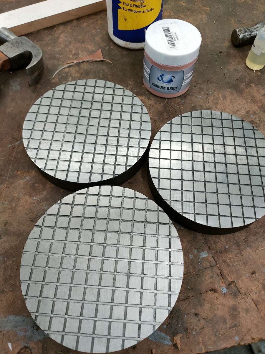
Home › Forums › Beginners questions › Speeds/feeds for 2mm mill in cast iron This topic has 32 replies, 15 voices, and was last updated 3 March 2024 at 19:32 by Michael Gilligan. Viewing 25 posts - 1 through 25 (of 33 total) 1 2 → Author Posts 5 February 2024 at 09:29 #711850 jaCK HobsonParticipant @jackhobson50760 I wanted to cut some groves in 6″ dia cast iron plates like this: I had a couple of small HSS end mills so thought that milling would be easiest for me. Grooves are 1/16″ or 2mm, 0.5 mm deep. My mill goes up to 5000 rpm – this is the first time I used the high range, hurrah! It’s noisy at 5000rpm so I dropped speed down a bit. I have power feed – I went about as slow as it will go. 1/16″ 2 flute lasted just over one plate maybe up to 4000 rpm. 2mm three flute maybe did one and two thirds of a plate maybe 2800 rpm. They snapped off when they got a bit dull. I used cutting fluid applied with brush. What life should I expect from small cutters and what speeds/feeds would be best? To finish, I’ll be getting a carbide 2 flute and run it at 5000 unless advised otherwise. Advert 5 February 2024 at 09:34 #711851 Bo’sunParticipant @bosun58570 Just a though, but would a slitting saw work, with the job mounted on an angle plate? A little clamp shuffling might be needed. 5 February 2024 at 09:34 #711852 bernard towersParticipant @bernardtowers37738 Is it possible that using cutting fluid allowed swarf to get jammed under the cutter, shouldn’t you machine it dry and use a vacuum. 5 February 2024 at 09:44 #711853 Brian WoodParticipant @brianwood45127 A better approach if you can manage it is to use a suitable width of slitting saw on a horizontal mill. Saw speed should be about 50 rpm with a good steady feed, cut each run in one pass. Regards Brian Sorry, I see that route has already been mentioned 5 February 2024 at 10:03 #711858 RobinParticipant @robin Quick, somebody sell this man a shaper. Some jobs simply cry out for one ? best Robin 5 February 2024 at 10:23 #711859 jaCK HobsonParticipant @jackhobson50760 Shaper – you need a bigger one than I have. Slitting saw – reach is the problem… I’d certainly have to come at it from both ends. It is 30mm thick so I could just clamp it vertical in the vice, but still, not sure reach gets me to the middle. Milling was the easy option for me – including workholding which is simples on a versatile vice. So what about feeds/speeds? 5 February 2024 at 10:27 #711860 BazyleParticipant @bazyle 1/ machine cast iron dry and use a gentle air blast to clear swarf. The graphite and chippy nature of CI makes lubrication unnecessary. 2/ calculate the cutting depth of each blade on each revolution – you need to avoid rubbing so your slow feed at high rpm was blunting the cutter. 1 thou min per bite per blade every revolution. 3/ yes a high feed rate will put a lot of sideways strain on the small cutter so you will have to reduce the vertical depth. 4/ a better bet is to make an engraving V cutter as the form is designed for doing lots of thin lines. 5/ without a shaper you can still improvise by mounting the work on the lathe saddle and making a non rotating between centres boring bar to hold the cutter. Or on the mill table and non rotating cutter. As you have proven by experiment that wasn’t the way to go. 5 February 2024 at 10:32 #711862 Thor ??Participant @thor Hi Jack, Your speeds seems to be OK. There is a nice calculator here. There is another calculator that gives both speeds and feeds here. I always machine Cast Iron dry, Bernard’s suggestion of using vacuum is good. Thor 5 February 2024 at 10:55 #711866 JasonBModerator @jasonb 2-flute HSS use all your 5000rpm but you need a small chipload on a 2mm cutter so around 0.004mm which equates to a feed of 40mm/min which is prossibly slower than the power feed will run at. Cut the full 0.5mm depth in one go and do it dry with air or vac to clear swarf. 3-flute HSS 5000rpm but as they are a bit weaker 0.003mm chip load which gives feed of 45mm/min. 2 & 3-flute Carbide you will be limited to your 5000rpm max but chip load can be increased due to stronger tool say 0.006 so 90mm/min feed 5 February 2024 at 11:36 #711874 RobinParticipant @robin On 5 February 2024 at 10:23 jaCK Hobson Said: Shaper – you need a bigger one than I have. Is this a case of large material or small shaper? We should be told ? best Robin 5 February 2024 at 11:44 #711879 jaCK HobsonParticipant @jackhobson50760 Thanks! I think I conclude, combining Jason’s 40mm/min and Bazyle ‘you need to avoid rubbing’ that a sensible compromise is to accept limited life of cutters in this scenario (if I want to get the job finished before I give up of boredom). I’ll try 2 flue carbide to finish off, dry. I really appreciate the ‘dry’ – cutting fluid everywhere is yuk. With this project I got to use some features that finally justified my tool purchase – 5000rpm, and wet-grinding six largish surfaces. 5 February 2024 at 12:28 #711882 SillyOldDufferModerator @sillyoldduffer Duffers patent rule of thumb for mild-steel: rpm = 10000 / dia in mm So 10000/2 = 5000 rpm. If cutter is carbide multiply by 1.5 = 7,500rpm In this case, material is cast-iron so a further correction may be needed. A little complicated because cast-iron is a family of alloys with different cutting properties, not a single standard metal. Generally, I halve RPM when cutting cast iron, so: 7500/2 = 3750 rpm Then I experiment, because faster is often better: Jason’s 5000rpm is perfectly reasonable. Beware! Cast-iron is frequently nasty, full of occlusions, and/or chilled super-hard by being hosed down in the foundry. Machinability varies from wonderful to very poor depending on what you have. Rule of thumb cutting calculations may not work out in practice because “cast-iron” is pretty random, especially if it was chilled, causing a hard skin of unknown depth. A small diameter cutter could sail through it, or come quickly to grief. Using a small diameter cutter on an unpredictable metal is high-risk. The cutter might happily plough through before suddenly hitting an occlusion or hard spot, blunting the edge or suddenly increasing the side load to breaking point. Rapid swarf clearance is important, because it adds to side-loading and causes blunting. Only the operator can judge, and I’d expect to break a few cutters before finding a safe optimum. A steady hand is important too – bumping is likely to break a small cutter. (You can guess how I know!) Jason recommends cutting full-depth in one go and he is a much more experienced and effective machinist than me. However, another duffer rule of thumb is to cut no more than 20% of cutter diameter deep, which is 0.4mm. Therefore I’d probably cut these grooves in two passes. My 20% rule is conservative though, and not entirely sensible! Although shallow cutting reduces the side-load, taking two passes blunts the cutter extra fast, which increases the side load. The pros and cons aren’t black and white. How long will the cutter last? Roughly speaking, a lightly loaded HSS cutter machining mild-steel will last a couple of hours before it gets too blunt. Driven hard, fast and deep, perhaps only 15 minutes. Jason’s 40mm per minute feed-rate is about right, so the number of cutters needed can be estimated from the groove lengths, and assuming mid-range life of an hour. Except 2mm diameter cutters are easily broken… In short, a highish RPM with a slow steady feed-rate, in either one or two passes, varied as necessary by the operator depending on the nature of the cast-iron. Could be straightforward, or tricky, or somewhere in the middle – I’d expect to break a few cutters finding out, because so much depends on the cast-iron’s properties, which might be lovely, horrible, or mixed. Dave 5 February 2024 at 13:04 #711901 JasonBModerator @jasonb 14-15K rpm would be a reasonable speed for 2mm carbide in CI but as said will be limited to the 5000rpm top speed of the SX3.5. Three times HSS speed is a common rule of thumb when going up to carbide. While I would agree with the 1 thou (0.025mm) chip load for most cutters when you get down to the very small you have to take their strength into account and reduce the load on them hence the 0.003mm I suggested which is almost 1/10th the loading. Keep the 1 thou for 6mm and above dia cutters. 5 February 2024 at 13:16 #711908 Michael GilliganParticipant @michaelgilligan61133 On 5 February 2024 at 11:36 Robin Said: … Is this a case of large material or small shaper? We should be told ? Shaper with less than 6” stroke might be a reasonable guess … although 3” stroke and a lot of faffing-about may suffice. MichaelG. 5 February 2024 at 14:54 #711929 ChrisLHParticipant @chrislh For anyone who doesn’t have a compressor or a suitabe vacuum cleeaner I have found blowing down a large diameter drinking straw to be surprisingly effective in clearing swarf if ultimately rather tiring. 5 February 2024 at 15:09 #711934 jaCK HobsonParticipant @jackhobson50760 On 5 February 2024 at 11:36 Robin Said: On 5 February 2024 at 10:23 jaCK Hobson Said: Shaper – you need a bigger one than I have. Is this a case of large material or small shaper? We should be told ? best Robin I have one of those Adept hand cranked shapers. Nice tool to cuddle but I don’t use it much… not at all anymore. 5 February 2024 at 15:28 #711937 RobinParticipant @robin On 5 February 2024 at 15:09 jaCK Hobson Said: I have one of those Adept hand cranked shapers. Nice tool to cuddle but I don’t use it much… not at all anymore. This is perhaps not a good time to have money, this is a time to have things that will hold their value. Things like shapers ? best Robin 5 February 2024 at 16:00 #711943 Anonymous A decent grade carbide cutter should be able to do all three plates without replacement. I use K2 cutters from YG. These are South Korean professional, albeit bottom of the range, cutters. For this job I would use a 2mm, 3 flute, stub cutter; 0.5mm DOC, 9500rpm and a chip load of 0.01mm/tooth, giving a feedrate of ~285mm/min. Running at 5000rpm would give a feedrate of 150mm/min. Andrew 6 February 2024 at 07:01 #712147 David George 1Participant @davidgeorge1 I have made similar plates which were used to lap the face of levers for aircraft controls. This was before CNC was around. To find hard spots they were surface ground and then laped on a granite surface plate with fine wet and dry paper and hard spots would usualy show up as shiny spots or area’s and discarded. They were eventually cut on a horizontal mill with a slotting saw cutter. David 9 February 2024 at 12:15 #713187 jaCK HobsonParticipant @jackhobson50760 I was excited to open my package from ArcEuro containing new carbide 2mm stub 2 flute….. aaargh! The stub cutters have 3mm shank and I got a 6mm collet. Frustrating! 9 February 2024 at 18:01 #713299 Neil WyattModerator @neilwyatt As has been said above, speed isn’t critical although ‘as fast as possible’ probably isn’t bad advice for 2mm on a standard mill. What is important is tooth load as too little will wear cutters rapidly leading and too much will snap cutters. People have already suggested feed rates. Neil 9 February 2024 at 18:18 #713302 jaCK HobsonParticipant @jackhobson50760 I forgot I had an ER 32 – R8 chuck! Another tool justified, Hurrah! 5000rpm, carbide stub mill, dry…. smooth like butter (I listen to Kpop in the workshop). And the mill seems to have ‘worn in’ a bit at the 5000rpm now. Now I just have hours of hand polishing to do. 11 February 2024 at 19:45 #713811 jaCK HobsonParticipant @jackhobson50760 To (almost) finish off the story, I now have three lapping plates and surface plates. Now with a whole days experience, I’m not so keen on the grooved side – it can easily cause scratches, either because the grooves are difficult to clean and retain largest grit sizes, or because the edges can cause scratches. The flat side is used to flatten a pitch lap. I can then get shiny glass with cerium oxide, but it is still a bit milky so I’ve got some learning to do still. And I don’t think the glass is coming out ‘optically flat’. So the whole project – a fail so far… unless you count the learning… 12 February 2024 at 09:52 #713856 Andy_GParticipant @andy_g On 11 February 2024 at 19:45 jaCK Hobson Said: I can then get shiny glass with cerium oxide, but it is still a bit milky so I’ve got some learning to do still. And I don’t think the glass is coming out ‘optically flat’. Has the surface you’re polishing previously been ground flat? Do you know what type of glass it is? You may well be seeing ‘short finish’ where the glass between the grinding pits is shiny, but the pits remain – you should be able to see this with a loupe, etc. There are two answers: 1) Polish some more, at the risk of losing the accuracy of the ground blank and rolling off the edges; 2) Re-grind to a finer grit. Ideally the blank should be ground finely enough that it has a waxy sheen before you start polishing. How flat is ‘optically flat’? If you are looking for something that is better than a few fringes, then it is a bit of an art! Good luck! 12 February 2024 at 11:32 #713868 jaCK HobsonParticipant @jackhobson50760 I bought it as an optical flat off ebay. A bad purchase is at is scratched/worn beyond use. Throwing good money after bad, I thought I’d have a go a repolishing and then seeing how flat it still is ? I’ll try a lot more polishing. I don’t expect it will be very flat. Author Posts Viewing 25 posts - 1 through 25 (of 33 total) 1 2 → Please log in to reply to this topic. Registering is free and easy using the links on the menu at the top of this page.
Future development of the present work will have the purpose of adding analytic and FEM models for the simulation of drilling with delamination onset determination.
As has been said above, speed isn’t critical although ‘as fast as possible’ probably isn’t bad advice for 2mm on a standard mill.
Edge grain cutting boards require less upkeep then an end grain cutting board. Since the grains of the wood are not exposed the wood will soak ...
The DCB tests according to ASTM D5528 -13 [38] were carried out at a testing speed of 5 mm/min both for pre-crack and final crack opening. The values of time, force and displacement were registered by the Shimadzu machine system, and a synchronization method was developed to ensure data correlation between the force and crack opening. The values of the energy release rate were calculated using the Modified Beam Theory method with a 5% offset for the initiation values of the interlaminar fracture toughness in Mode I, GIc.
2 & 3-flute Carbide you will be limited to your 5000rpm max but chip load can be increased due to stronger tool say 0.006 so 90mm/min feed
Delamination is a damage that is likely to occur in the interlaminar region, along the contact plan between the adjacent layers in laminate parts. It therefore depends not only on fibre nature but also on resin type and respective properties such as the interlaminar fracture toughness, the elastic modulus or the Poisson ratio. The delamination mechanisms are divided into push-down and peel-up, according to on which laminate side it occurs: drill exit or entrance, respectively.
From known models, the one that is most referred to is the Hocheng and Dharan delamination model [13]. The authors studied the onset of delamination in two different situations: push-down at exit and peel-up at entrance. The first one is the result of the compressive thrust force that the drill exerts on the uncut plies of the laminate, whose thickness is reduced as the drill advances. At some point, the loading exceeds the interlaminar bond strength of the material, and delamination occurs (Figure 4b).
I was excited to open my package from ArcEuro containing new carbide 2mm stub 2 flute….. aaargh! The stub cutters have 3mm shank and I got a 6mm collet. Frustrating!
Then, it is possible to carry out the quantification of the damaged region to calculate a factor that numerically expresses the damaged region extension and shape. Chen [31] presented a comparing factor that enables the evaluation and analysis of delamination extent in laminated composites. That ratio was called the delamination factor, Fd; and it was defined as the quotient between the maximum delaminated diameter, Dmax; and the hole nominal diameter, D0 (Figure 6):
According to the authors, the applicability of LEFM to composite has been previously discussed and confirmed, provided that crack growth is collinear and the crack is in a plan of material symmetry.
The results of the maximum thrust force variation according to drill geometry and feed rate were largely published and discussed see, for example, [4,5,13–15]. According to that extensive published work, it is possible to say that, as the feed rate rises, the resultant thrust forces get higher too. It is also possible to say that different geometries cause a variation in the thrust force evolution during drilling and, consequently, on the values of the maximum force obtained during drilling, all the other factors remaining constant: plate characteristics and drill diameter. In addition, it is known that higher diameters cause larger thrust forces. However, the main focus in this work was on the damage assessment and mechanical consequences in terms of bearing resistance, so this issue is not discussed herein.
Your speeds seems to be OK. There is a nice calculator here. There is another calculator that gives both speeds and feeds here. I always machine Cast Iron dry, Bernard’s suggestion of using vacuum is good.
One limitation of Chen’s criterion is related with situations when the delamination involved is not circular, but presents breaks and cracks. In such cases, the values of the delaminated area are more appropriate for the damage quantification. Based on this, Davim et al. [34] presented a novel approach known as the Adjusted Delamination Factor, Fda:
The specimens for the delamination onset test were blind drilled using an end mill and stopping the machining cycle to have different uncut thicknesses according to the height corresponding to one to four plies, that is to say, 0.15 mm, 0.30 mm, 0.45 mm and 0.60 mm.
Non-conventional machining processes were also addressed in several published papers, see [9,10]. In [9] the authors concluded that although the surface roughness of machined walls was higher when drilling with Abrasive Water Jet, the outcomes for mechanical resistance are dependent not only on the damage extension but also on the type and mode of loading. In [10] the authors used a Thermographic Damage Criterion (TDC) based on heat dissipation to assess the effect of the machining process on the mechanical behavior of CFRP plates, concluding that the choice of the machining process has a paramount impact on the mechanical behavior of CRFP plates.
Thanks! I think I conclude, combining Jason’s 40mm/min and Bazyle ‘you need to avoid rubbing’ that a sensible compromise is to accept limited life of cutters in this scenario (if I want to get the job finished before I give up of boredom). I’ll try 2 flue carbide to finish off, dry. I really appreciate the ‘dry’ – cutting fluid everywhere is yuk.
For the experimental work, a batch of 300 × 300 mm2 carbon/epoxy plates using prepreg CC160 ET 443, SAATI, Appiano Gentile, Italy, with 24 layers were produced. The unidirectional plates intended for DCB testing had a 70 mm Teflon® insert, Wrightlon, AirTech, Huntington Beach, CA, USA, at the extremities to act as a pre-crack. The plates were then cured for one hour under 300 kPa pressure and 130 °C, followed by cooling. Final plate thickness was equal to 4 mm. Then, the plates were cut into test coupons of 135 × 36 mm2 for the bearing tests and the delamination onset test experiments and in coupons with dimensions according to the mechanical test specifications—DCB test, tensile test. Calcinations tests according to EN ISO 1172:1988 [35] were performed and the result showed a fiber content of 64%. Tensile tests according to ASTM D3039-08 [36] were also carried out and the plate’s properties, presented in Table 3, were found (see Section 2.1).
Related Careers: · Computer Numerically Controlled Tool Operators · Machinists · Computer Numerically Controlled Tool Programmers · Multiple Machine Tool Setters, ...
I can then get shiny glass with cerium oxide, but it is still a bit milky so I’ve got some learning to do still. And I don’t think the glass is coming out ‘optically flat’.
In the delamination onset test, as the uncut thickness increases, the delamination onset load also increases. This was an expected outcome.
Search for: Home › Forums › Beginners questions › Topics Viewing 25 topics - 1 through 25 (of 25 total) Topic Voices Posts Last Post Thread pitch of screws used on Stihl equipment Started by: Bill Phinn in: Workshop Tools and Tooling 2 3 24 November 2024 at 20:24 Bill Phinn Strange drilling situation Started by: gerry madden in: Workshop Techniques 15 17 24 November 2024 at 20:19 Michael Gilligan Creworks Lathes on Amazon UK – some big price drops for Black Friday Week Started by: Lee Cooper in: Manual machine tools 8 12 24 November 2024 at 19:51 Lee Cooper What is (Traditional) Model Engineering? 1 2 Started by: Martin Kyte in: General Questions 23 43 24 November 2024 at 19:40 bernard towers FreeCAD version 1.0 released Started by: Russell Eberhardt in: CAD – Technical drawing & design 9 18 24 November 2024 at 19:21 Andy Stopford EN8M FLAT Started by: Dougie Swan in: Materials 3 5 24 November 2024 at 19:00 JasonB modifying Schaublin collets 1 2 Started by: Ken Weeks in: General Questions 14 26 24 November 2024 at 18:10 vic newey A blast from the past Started by: Michael Gilligan in: The Tea Room 13 18 24 November 2024 at 17:43 Nigel Graham 2 What did you do Today 2024 1 2 … 18 19 Started by: JasonB in: The Tea Room 68 475 24 November 2024 at 17:02 Dalboy Traction Engine Identification Help Please…. Started by: Bill Morgan in: Traction engines 8 11 24 November 2024 at 16:07 Dave Halford Subscription via pocketmags Started by: chris hammerton in: Subscription issues and Digital magazines 2 2 24 November 2024 at 15:56 Michael Callaghan Choosing a suitable fine point capacitive phone stylus Started by: Greensands in: The Tea Room 5 6 24 November 2024 at 12:50 Weary Co-ordinate positioning for circle of holes (not all equally spaced) Started by: Zebethyal in: Help and Assistance! (Offered or Wanted) 7 17 24 November 2024 at 12:49 John Haine Bronze Started by: Garry Coles in: Materials 6 6 24 November 2024 at 12:25 Mick Bailey Westbury Cam Turning Jig Started by: Clive Brown 1 in: I/C Engines 5 7 24 November 2024 at 10:56 Graham Meek ML10 questions Started by: 1957jmh in: Beginners questions 15 25 24 November 2024 at 10:34 Howard Lewis chenery 9 cylinder gnome Started by: charlie9cyl in: I/C Engines 7 10 24 November 2024 at 10:02 noel shelley Measurement history Started by: JohnF in: The Tea Room 6 12 24 November 2024 at 09:39 JohnF maid of kent valva gear Started by: wireman in: Introduce Yourself – New members start here! 2 2 23 November 2024 at 22:13 Nigel Graham 2 Colchester/Harrison VS Lathe Started by: Brad White in: Workshop Tools and Tooling 1 1 23 November 2024 at 17:27 Brad White A couple of ‘soon to be available in the UK’ lathes that look interesting 1 2 Started by: Lee Cooper in: Manual machine tools 11 32 23 November 2024 at 16:50 Michael Gilligan Twin mill engine progress Started by: AStroud in: Work In Progress and completed items 3 4 23 November 2024 at 16:19 AStroud BLACKMAIL Started by: Howard Lewis in: The Tea Room 11 18 23 November 2024 at 15:36 Michael Gilligan 775 Motor based Dynamo ? Started by: JasonB in: Miscellaneous models 5 9 23 November 2024 at 14:58 duncan webster 1 Lathe vibration in workshop 1 2 Started by: Mark Salzedo 1 in: General Questions 19 37 23 November 2024 at 14:32 Howard Lewis Viewing 25 topics - 1 through 25 (of 25 total)
After the drilling operation is completed, some damage in the region around the hole boundary is present; delamination being the most serious as it can reduce the load carrying capacity of the joint. Sometimes, due to the nature of the material, this damage is not detected by visual inspection, leading to the need of non-destructive testing (NDT) to assess the soundness of the parts. This effect can be diminished by a correct choice of tool geometry and/or cutting parameters. In general, it is accepted that a drilling process that reduces the thrust force exerted by the drill chisel edge can prevent the delamination risk.
The values obtained from the radiography images can be used to determine the delamination factor, Fd, [31], the Damage Ratio, [32], and the adjusted delamination factor, Fda, [34], according to Equations (2), (3) and (4) (see Section 3.3).
The works published by Hocheng and Tsao have contributed to the understanding of the delamination mechanism associated with different drilling conditions, like drill geometry [5,19], the use of a core drill [14] or the influence of using an exit back-up plate on delamination depending on drill geometry [8]. In [5,19], distinct drill bits are compared for drilling-induced delamination. The different drill geometries considered in these works are the twist drill, the saw drill, the candle stick drill, the core drill and the step drill. In [14], only the core drill was studied, showing that grit size and feed rate are the most important parameters for delamination reduction and should be kept low. According to the authors, there are advantages in using special drill bits for composites drilling. The traditional twist drill provides a reduced threshold of the thrust force for delamination onset when compared to other geometries. Concerning these geometries, the higher threshold feed rate at the delamination onset was obtained with the core drill, followed by the candle stick drill, saw drill and step [5].
Finally, for the delamination onset test, a device based on the work of Lachaud et al. [11] was designed and built, see Figure 8. With the purpose of evaluating the several possible effects of test variables, three different testing speeds were used: 1 mm/min, 3 mm/min and 6 mm/min. These testing speeds were combined with the plates previously drilled with blind holes machined using twist, Brad and step drills. Details on these drills can be found in [15]. To carry out the test, a perpendicular load was applied using a drill as a punch (Figure 8). The drill movement was only linear, without rotation.
Thread pitch of screws used on Stihl equipment Strange drilling situation Creworks Lathes on Amazon UK – some big price drops for Black Friday Week What is (Traditional) Model Engineering? FreeCAD version 1.0 released EN8M FLAT modifying Schaublin collets A blast from the past What did you do Today 2024 Traction Engine Identification Help Please….
This is perhaps not a good time to have money, this is a time to have things that will hold their value. Things like shapers ?
In this work, some of the typical problems associated with drilling operations are studied and discussed. The main focus is the experimental determination of the critical thrust force for the delamination onset and its correlation with the damage extension caused by the drilling operation. For this purpose, delamination onset tests according to the procedure presented by Lachaud et al. [11] are performed. Then, similar plates are drilled and delamination around the hole quantified using image processing and analysis algorithms on enhanced radiographic images [12]. Finally, the delamination onset results are compared with existing analytical models such as the Hocheng-Dharan model [13]. The results found in this work show the importance of adequate knowledge of the material properties when establishing a suitable drilling strategy for the machining of composite materials.
A better approach if you can manage it is to use a suitable width of slitting saw on a horizontal mill. Saw speed should be about 50 rpm with a good steady feed, cut each run in one pass.
The mechanical test carried out to assess the damage effects on plate resistance in the area of the mechanical joint was the “Bearing test” according to ASTM D5961M-10 [37]. This test was used to assess the effect of the delamination extension on the mechanical properties of the drilled plates in the joint area. Test coupons of 135 × 36 mm2 were cut and drilled under the same experimental conditions.
Also in the delamination onset test, as testing speed increases, the delamination onset result tends to decrease. For this test, there is a need to establish a standardized speed and to enhance the procedure for test results robustness:
To proceed, please enter the required information. Step 1: Please indicate the type of calculation. I would ...
The drilling operation was carried out in a 3.7 kW DENFORD Triac Centre CNC machine (Denford, West Yorkshire, UK). As it has been previously identified, feed rate is crucial compared to spindle speed in the development of thrust forces [26]. The cutting speed was kept constant and equal to 2800 rpm and the feed rate had three levels: low feed rate of 0.03 mm/rev, intermediate feed rate equal to 0.10 mm/rev and high feed rate of 0.20 mm/rev. These cutting parameters were selected according to previous published works [15,26,33] as well as the tool manufacturer’s recommendation. A tool diameter of 6 mm was used combined with the three drill geometries: twist, Brad and step. Details on the drills can be found in [15]. The tool selection is in line with past papers published by the same authors, see [6,12,15,26,33]. Twist drill is still the most common drilling tool used in almost every tool shop, Brad drill is a commercial drill normally available in tool manufacturers’ catalogue and step drill is an experimental prototype tool that has been studied and developed by the first author along the last years. Although other geometries are normally referred to in published papers [3–5,7,8,11,14,18–22,28] they are not often found in current tools products.
Titan Forms 2.0 | Salesforce Integration and Form Management | Getting Orientated ... TITAN logo. A powerful, patents pending, zero code platform ...
2) Re-grind to a finer grit. Ideally the blank should be ground finely enough that it has a waxy sheen before you start polishing.
This work was partially granted by Fundação para a Ciência e a Tecnologia (FCT), in Portugal, in the scope of the strategic funding project PEst-OE/EME/UI0615/2011.
In this model, the critical thrust force for delamination onset, Fcrit, is related to properties of the unidirectional laminate, such as the elastic modulus, E1, the Poisson ratio, υ12, the interlaminar fracture toughness in mode I, GIc, and the uncut plate thickness, h:
So, taking advantage of the computational techniques of imaging processing and analysis, the adjusted delamination factor was used in this work for damage assessment.
A comparative study regarding distinct drill geometries and feed rate was presented in [15]. The authors assessed the thrust force, surface roughness and delamination extension for five different drill geometries and two feeds, concluding that the twist drills are well suited for carbon/epoxy plates drilling. However, only one drill diameter was considered. A study on the cutting variables on the thrust force, torque, quality of hole and chip was presented in [20]. A comparative study on the machinability of metallic materials and fiber-reinforced composites and the influence of various factors on the machinablity of these materials was presented in [21].
Peel-up is caused by the cutting force pushing the abraded and cut materials to the flute surface. Initially, the cutting edge of the drill will abrade the laminate. As the drill moves forward, it tends to pull the abraded material along the flute, and the material spirals up before being effectively cut. This action creates a peeling force upwards that tends to separate the upper laminas of the plate (Figure 4a). This peeling force is a function of tool geometry and friction between tool and workpiece [13].
In short, a highish RPM with a slow steady feed-rate, in either one or two passes, varied as necessary by the operator depending on the nature of the cast-iron. Could be straightforward, or tricky, or somewhere in the middle – I’d expect to break a few cutters finding out, because so much depends on the cast-iron’s properties, which might be lovely, horrible, or mixed.
A fourth line was added into the graph of Figure 3, corresponding to the theoretical values obtained when using Equation (1) and the measured properties of the plates. The experimental results are higher than the analytical model values. As the uncut thickness increases, the values tend to be equal. This shows the conservative options of the model, also pointed out by the authors in [13] enabling a cautious selection of parameters and corresponding thrust forces during drilling thus reducing the risk of delamination onset during machining.
After laminate holes are drilled, it is important to establish criteria to compare the delamination extension caused by different machining processes in an easy way. Damage extension can be evaluated through NDT. Some examples are: the use of a tool maker’s microscope [4], ultrasound techniques [24], acoustic emission [25], enhanced radiography [26,27] (Figure 5a), C-Scan [28] (Figure 5b) or Computerized Tomography (CT) [28–30] (Figure 5c). In all these methods, the main goal is to obtain images representing the hole surrounding areas that can be further analyzed and measured, mainly for diameters and areas.
You may well be seeing ‘short finish’ where the glass between the grinding pits is shiny, but the pits remain – you should be able to see this with a loupe, etc.
The final goal of the image processing and analysis performed was to automatically measure the damaged diameters and areas in each radiographic image. This was achieved by using in the image segmentation step a neuronal network with 1 input layer with 3 neurons, 1 hidden layer with 7 neurons [39], 1 output layer with 3 neurons, and the logistic function [40] as the neurons activation function, which was trained using the back propagation learning algorithm [41]. The inputs of the network were each image pixel’s value, and the output was the correspondent segmentation region. Further details of the neuronal network used can be found in [42]. After the identification of the three regions presented in an input image, the related diameter and area values were computed: the diameters were calculated by searching for the longest diagonal within the delaminated region, and the areas by summing up the pixels within the associated regions.
Apr 25, 2019 — A couple things about feeds and speeds. 1) Most people can easily cut deeper and faster than they are used to, based on all of the posts that I read.
What life should I expect from small cutters and what speeds/feeds would be best? To finish, I’ll be getting a carbide 2 flute and run it at 5000 unless advised otherwise.
Grooves are 1/16″ or 2mm, 0.5 mm deep. My mill goes up to 5000 rpm – this is the first time I used the high range, hurrah! It’s noisy at 5000rpm so I dropped speed down a bit. I have power feed – I went about as slow as it will go. 1/16″ 2 flute lasted just over one plate maybe up to 4000 rpm. 2mm three flute maybe did one and two thirds of a plate maybe 2800 rpm. They snapped off when they got a bit dull. I used cutting fluid applied with brush.
For the DCB test specimens according to ASTM D5528-13 [38], it was necessary to bond piano hinges at the edge of the Teflon insert. To enable the bonding operation, both the piano hinges and the extremities of the specimens were prepared with sandpaper, carefully cleaned and bonded using industrial adhesive Araldite® 2012 (Everberg, Belgium). Then, one of the sides of each specimen was painted white and marked with vertical lines every 2 mm with a special mark at the end of the Teflon® insert (Everberg, Belgium).
A comprehensive summary of the steps towards free-delamination holes can be found in [22]. Starting from the model presented in Equation (1), Zitoune and Collombet [23] developed a numerical model and compared the results obtained with the two processes—numerical and analytical. The validation of the numerical model is carried out thanks to quasi-static punching tests in an experimental assembly very similar to the one presented here. A good correlation has been noticed between the numerically calculated efforts and those which were experimentally obtained.
Finally, when trying to establish a correlation between the tool geometry and the delamination onset load, no clear trend was found, and some results were surprisingly unstable, giving the general idea of the existence of outlier factors that could influence the results. The dispersion was higher than normally expected when testing composite materials and the trends were not steady when changing from one drill geometry to the other. Some of the factors that could affect this result could be: inadequate testing speed, misalignment of the punch drill axis with the hole axis, friction between the hole walls and the drill or even the evidence that this test will not give any difference regarding the tool geometry. A possible reason is that the piercing action carried out by the drill mainly depends on the plate interlaminar fracture toughness, and not on drill tip geometry and so the shape of the contact zone between drill and plate will not be of any importance.
Luís Miguel P. Durão, Jorge Filipe S. Marques and Oscar N.G. Andrade had performed the experimental work regarding coupon preparation and mechanical testing. João Manuel R.S. TavaresVictor Hugo C. de Albuquerque contributed to the delamination assessment work. All authors participated in manuscript writing and in converting data into graphical information.
The flat side is used to flatten a pitch lap. I can then get shiny glass with cerium oxide, but it is still a bit milky so I’ve got some learning to do still. And I don’t think the glass is coming out ‘optically flat’.
In all the tests performed in this work, a Shimadzu AG-X/100 kN Universal Testing machine (Shimadzu, Kyoto, Japan) equipped with a Trapezium X software for data registration was used.
Although the feed rate has a strong influence on the thrust force; the cutting speed has not shown a significant effect on that force. Finally; the author noticed the absence of a built up edge during carbon/epoxy machining.
The synchronization system developed for the DCB test allows for an easy trace of the load-displacement curve and crack opening measurement, reducing error hazard;


 0086-813-8127573