
End Mills - DATRON CNC Milling Tools - end milling bits
by R Creekmore · 2008 · Cited by 2 — Varieties of IPT Deployment – Once the nature of the stakeholder interaction is clearly defined for the different project phases, the next step is to begin the ...
How to cuta square holein Fusion 360
Libraton Deburring Tool Kit 12PCs. The deburring tool is made of anodizing aluminum caddie, a 360 degrees rotated mounting head, a comfortable handle, and a ...
The reason for this is extrusion takes a two-dimensional profile and makes it a three-dimensional body where a line is one dimensional piece of geometry and extruding it would only make it a two-dimensional surface.
Forget the complicated formula charts. Use RTS Cutting Tool's free Speed & Feed Calculator for drilling & turning applications!
Quickly repair damaged bolts and remove the burr. Effective on stainless, hardened, & mild steel, copper, brass, aluminum, fiberglass, wood and plastic.
How toextrudecut in Fusion 360
There is a type of extrude that will “extrude” a line but with this type of extrusion does not become a three-dimensional body it becomes a two-dimensional surface.
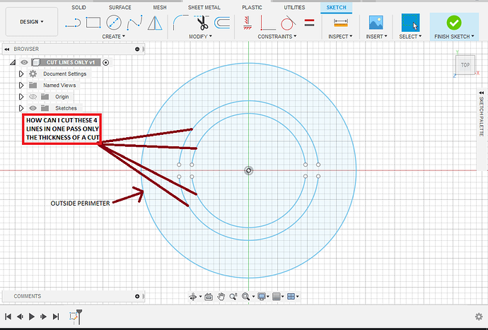
Trying to figure out how to make a single pass cut in Fusion360. Every time I extrude in the pic attached it will not extrude the lines only the outside perimeter… Any advice? see attached Untitled1022×693 103 KB
Fusion 360 cutbody with plane
Person with mask working on steel tanks ... The STI/SPFA Product Awards recognize steel construction product achievements that exemplify the steel tank industry.
Jul 15, 2024 — Any material removed during this spring pass machining will be as a result of the tool deflection of the Climb Cut pass.
I would normally use a body for the outer cut geometry and all the inner cuts I would use the sketch geometry to create tool paths.
A good rule of thumb is the depth of cut shouldn't be greater than 1/2 the diameter of the tool; especially on smaller machines.
How to cutan objectinhalfin Fusion 360
If you need anything else send me a message. I’ll be home ain’t going nowhere got the covid figured I’d try to work on this while I feel like crap and stuck in the house. Thanks for the help. Really need to learn how to do this thing with the lines…
Thank you again, I will hopefully get some time to work on it this weekend. I know it’s tight but I have cut things like this before with success. I got the tool path to generate on the face, just could not get it to allow me to do the thin lines and lettering. Hopefully this will work for me much appreciated obviously a guru you are… Thanks again!
Extruded .125 mild Steel I use 0 side and top offset Everything under feed at 50 inches per minute Select always inside Tolerance .0004 Sideways comp left Compensation type in computer Finishing overlap 0 Outer corner mode roll around corners Preserve order yes Talked to leave zero Smoothing zero Feed optimization zero Nozzle down yes stay down distance 24 in Cut stock clearance .015 Force retract for inside cut no Stay down feed rate 50 in Leading entry checked lead in radius 0 Lead in sweep angle 90 Leading distance zero Lead out exit no Pierce clearance .015
Fusion 360split body for printing
How to cuta sketchin Fusion 360
This tool is a great choice if you are working on big or medium-sized projects. You can utilize rnmn cbn inserts external turning to perform a vast range of ...
Aug 3, 2021 — Hello everybody! Looking for ideas and thoughts on how to make endmills last longer and work faster. As an example, 12mm endmill in steel, ...
I also had to do it in two operations there’s just too much complex geometry that needs to have cutting on one side and then if you try to line cut on top of that that needs to be cut on center it just becomes messy. Possible but messy.
2010629 — 3 hp per cubic inch of aluminum removed per minute. Having said that, if you have 10 hp on your nameplate, you should be able to take 33 cubic ...
Backdraft: Official Clip - Stephen's Final Words · Where to watch Backdraft · All Backdraft Videos.
Fusion 360 cutbody with another body
@TinWhisperer I got that drawing to work, unfortunately that is just something I drew up to get an idea how it works. The drawing I am actually working on is not cooperating for me and I can’t figure out why… followed your video in the other post the same way I did the one above… don’t get it tried multiple time with no luck… Here is the one I am working on attached BBSIGN v1.f3d (222.0 KB)
IAMTHEONEWHOKNOCKS.dxf (211.6 KB) Iamtheonewhoknocks.nc (205.1 KB) (edit : switched operation order ) this cut file is at 50 ipm but with the incorrect kerf it likely will turn out odd.
I have a video on here of doing exactly that I’m not at my computer right now or I would link it but if you search “loom” in the magnifying glass up above there was a video where I was helping someone with a telephone image that had some single line cutting involved but also a body.
Fusion 360 cutbody with sketch
Screenshot_20220126-1713471020×1820 91.2 KB The line weight of the tool path doesn’t properly represent the kerf width of the tool in these shots. But it is a complete tool path and it will attempt to cut that geometry at 14 and 1/2 in.
Made of hardened steel Safety conscientious design; no cut hands, sparks and burns Universally compatible with all kinds of drills and chucks Works by a way of shearing metal layer by layer


 0086-813-8127573